Additional reading about pin types in general: Electrical type of schematic symbol pins (KiCad 4 and KiCad 5)
A good explanation about power symbols can be found in this stackexchange answer by @Seth_h
KiCad does check if every component is connected to supply lines (*1) as a missing supply is a common mistake to make. Getting the error “ErrType(3): Pin connected to some others pins but no pin to drive it” means that KiCad thinks that some supply pin is not properly connected. Either because there is a missing connection or because KiCad has not been told where the circuit is supplied.
The later is the most likely cause for new users. This means the problem is typically easily solved by adding a “PWR_FLAG” symbol to the schematic. An examination of the Electrical Type assigned to the symbols pins will explain why KiCad has PWR_FLAGs.
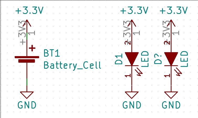
Here is a simple schematic using two devices without the PWR_FLAG symbol that passes the ERC without error.

Here are the Pin Types for the two devices:


From these, the next question then becomes, “Where are the Power inputs”?
The ERC uses the VCC and GND symbols as “inputs”.


There is a very simple reason for this if even at first this does not seem to make sense. Schematics are often drawn with multiple instances of the same voltage sources and ground points.
In the above schematic, with the +3.3V and GND symbols pins designated as “inputs” there is no conflict in the ERC. Note that there would have been a conflict if the 3.3V symbols pins were designated as “outputs”. This is shown in the following example:

The most common issue new KiCad users have is the relationship between connectors, devices, and PWR_FLAGs.

If the KiCad library symbol for the regulator is correct, it should have it’s pins Electrical Type assigned as shown in the following diagram:

In the very first example schematic, the battery was clearly a Power “output”. There were no ERC issues because the battery “output” was applied to other symbol “inputs”. In this second schematic, it is not clear that the Conn_01x02 is an “output” device. The library symbol could be changed to re-assign the pins as “outputs” and this second example schematic would pass the ERC; until the same Conn_01x02 symbol was used in a second instance and connected to pin 3 of the above regulator.
KiCad has a rather unique tool to solve these ERC issues between symbols. KiCad’s creative solution is the PWR_FLAG! (The PWR_FLAG is found in the power library supplied with kicad. Use the “place power port” dialog and type PWR_FLAG into the search field. Place it like any other power symbol.)

Adding the PWR_FLAG to the schematic and connecting separate ones to the voltage source symbols and ground points will create a schematic that is ERC compliant.

The PWR_FLAG tool allows KiCad to retain it’s flexibility in design with generic schematic library symbols, and still provide a quality ERC.
NOTE: Although both flags have the same text, “PWR_FLAG”, they are NOT connected together as they are internally assigned a different FLAG/NET_ NAME when they are placed.
If you do not want to use kicad supplied symbols at all then you can easily create your own PWR_FLAG symbol. It is nothing else then a symbol with one pin that has the type “power output”. In addition its reference designator starts with “#” to ensure kicad does not try to connect it to a footprint. Enabling “this is a power symbol” will ensure that it is shown in the “add power port” dialog.
Footnotes:
[1]: KiCad can only detect a missing supply if the supply pins have been given the electrical type “power in”. Luckily power symbols (power labels or power ports) are defined as power input and therefore require nets that use this symbol to be powered.