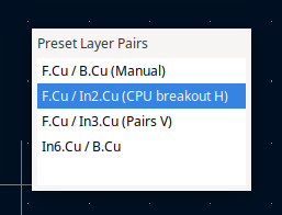
Layer pairs can be added to a preset list. “Enabled” pairs, along with the currently-set pair if not itself a preset, can be cycled with the “Shift+V” hotkey:

Layer pairs can be added to a preset list. “Enabled” pairs, along with the currently-set pair if not itself a preset, can be cycled with the “Shift+V” hotkey:
There is a new Shape Modification tool next to Fillet and Chamfer: “Dogbone” corner relief for cutouts that have to fit something with square corners (specifically: sharper than the edge-routing milling bit, often 1 or 2mm):
The Position Relative tool can now use an arbitrary point as the reference (which can be snapped to objects)
In eeschema, net colors defined by netclasses can now be displayed in a highlighting style, by selecting the ‘Highlight net colors’ in the netclass setup panel (from discussion in Is it possible to make netlist colors look more like Altium? - #4 by JamesJ)
Note that the net color highlighting setting has been moved to the application settings, in schematic display options:
In the PCB editor, there is now an at-cursor indicator showing what exactly the cursor is snapping to, which also now includes intersections between lines, circles and arcs:
This can be useful when constructing geometry. For example, you can draw a hexagon:

More importantly for footprint drawing, it is easier to make something like this using just a couple of construction lines and circles:
Front and back designations for user layers. (If marked as front or back, they will be flipped when the board view is flipped.)
DNP indications when plotting. (Note that “Cross-out” will also strikeout the reference designator.)
There is a new tool for creating “real” outsets from a limited set of shapes: segments, rectangles, circles and pads (except trapezoidal or custom shaped). If you choose rounded corners, these use real arcs rather than interpolated polygons:


When possible (i.e. no arcs), you also get polygons back, which means you can do boolean operations on them. This means quite a few common fiddly operations in footprint drawing become more straightforward:
When possible (mostly for rectangle-based outsets), it can be asked to attempt to round outwards to some grid multiple. This can be used, for example, for rounding courtyards to the IPC-recommended 0.01mm grid rather than manually bumping things around by 0.005mm here and there.
It can also be used (with a little manual trimming of end caps) for, say, snake-shaped slots:

The ‘bounding hull’ tool still exists and remains the only way to handle arbitrary polygons (in particular ones with holes or concave corners).
You can set the point that a reference image in the schematic and PCB editors scales around. This allows you to keep a certain point in the image fixed while you scale the image to match another point:
There is a Bezier curve creation tool in the schematic and PCB editors:
Like the arc tool, there are some guide lines in the PCB editor, and by default it chains them as tangent to each other. The backspace key works in the same way as the arc tool. The interactive edit guides are not (yet) in the schematic editor (same for arcs). Beziers were already importable and editable once imported, but now they can be created from scratch.
There is an option in symbol editor to keep pins attached by their “roots” to rectangles when dragging edges by the central handles:
You can bypass it when needed using the corner handles.
If the shape is shared in all units, attached pins in all units are moved. If the shape is only in a single unit, only the pins in the same unit move with it.
It is now possible to set component classes on symbols in eeschema. Directive labels attached to a rule area can now take a ‘Component Class’ field - any symbols within the rule area will be assigned that component class. The ‘Component Class’ field can be set directly on symbols too:
Symbols can have more than one component class, taking on any that are defined directly on the symbol (or any of its sub-units), or from any directive labels attached to any rule areas which contain the symbol.
In the PCB editor, component classes are attached to the symbol’s footprint:
There are two new DRC expressions / functions to support querying component classes:
(condition "A.ComponentClass == 'CLASS_1,CLASS_2'")
to test against the full list of component classes, where the composite component class is a comma-delimited list in alphabetical order), and
(condition "A.hasComponentClass('CLASS_1')")
to query against a specific component class.
In KiCad 9, plated through-hole pads and vias will be displayed differently than in previous versions. Now, the copper annular rings for these items will be shown in the same color as other copper items on the same layer.
Blind/buried vias and microvias now are drawn with the colors of their start and end layer in the drill hole:
These changes were made to make dense and complex boards easier to understand, and as part of preparing to add support for complex padstacks (where vias and pads may have different sizes and shapes on different copper layers) to KiCad
KiCad now supports PTH pads with different copper shapes on different layers. This is one type of custom padstack; other padstack features will be added over time.
There are now optional indicators (toggled in the view menu and schematic editor settings) to indicate when pins have alternate modes available, as this was otherwise only visible by noticing the appearance of an entry in the context menu:

In the PCB editor, you can toggle the session locked item prompt from settings:

Now you don’t need to keep the lock prompt on when you don’t really want to to avoid of having to restart if you want them back.


