How do I tell PCBnew that a polygon generated by “Draw a graphic polygon” is intended to be part of the “+5V” net, so having that polygon overlap some pads on the “+5V net” is OK?
Details:
Voltage regulator datasheets typically show an example layout with thick, chunky connections for high-current nets between a chip and the parts around it.
In KiCad 6 PCBnew layout, it seems natural to use the “Draw a graphic polygon” tool (CTRL+shift+P) to draw those shapes on the top or bottom copper layer.
But then the DRC gives me a “clearance violation” between that copper layer and pads on the “+5V” net. Apparently DRC doesn’t realize that graphic polygon should be part of the “+5V” net.
(While this isn’t exactly what I wanted, I must admit that the current behavior is vastly better than
“DRC not complaning with copper polygons”
)
For DRC to work properly, must I re-draw all such graphic polygons as a “zone” with the “Add a filled zone” tool (Ctrl+Shift+Z) and remove all (non-zone) “graphic polygons” from the copper layers?
I agree. But some of these questions get into areas where my foundation in the software is not so good. I also question why the software would make a copper polygon on the board that is not connected to a net. I think that copper which is electrically floating is generally bad practice but there may be special exceptions.
It’s a choice you get when you start the filled zone, which net, if any, to connect the zone to. So the software lets you do advisable or inadvisable things.
Thanks. If anyone knows of a good reason why they would want a floating copper zone I would like to hear about it. I can think of:
A copper area getting connected by a screw in later assembly, or something similar…
Copper text. But these days our boards mostly have silkscreens. Not sure why copper text would be needed. And copper text is not a zone.
My copper polygons cover most of several pads – in particular, one copper polygon nearly completely covers the “+5V” end of one capacitor and the “+5V” pin of one voltage regulator. Those copper polygons are definitely not floating, and in fact the DRC complains that that polygon is touching those pins. (In my opinion incorrectly complaining. I feel DRC should only complain if that polygon gets too close to any other net, any net that is not “+5V”.)
“Why copper text”?
I don’t see how that’s relevant to this thread – perhaps you should ask that as a separate question – but because you asked:
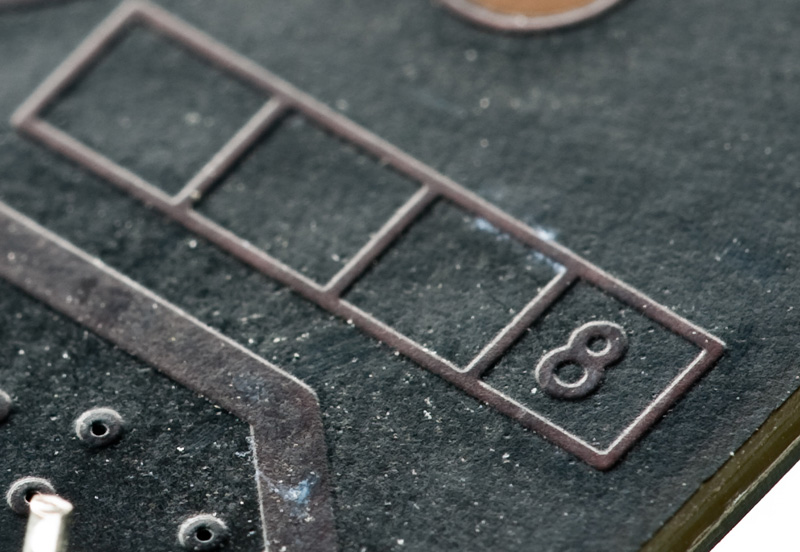
Many people write the layer number in copper text on every layer because many PCB design guides recommend a “layer indicator block” in – see
For example, copper has better resolution than silk and no offset. On a small board, say, 10x10 mm it may not be useful to use silk at all, but there may be some room on a copper area. And copper text looks way more cooler than silk
I came to KiCad from Altium recently and I’m still learning. I am very impressed with version 6 and have donated to KiCad in the last drive to help out.
A few days ago, I struggled to draw a filled rectangle in a copper layer and assign a net to it, just as you described.
What I found:
You can draw a graphics shape in a copper layer.
Right click on it and select the command: [Create from Selection].
Now, you can make the shape into a zone, keep out, traces, etc.
Keep in mind that the original shape is still there, under the newly created one (You may want to delete it).
I tried it in PCBNEW and Footprint Editor and it works beautifully!
You certainly put in some effort to find that list of 8 references.
But I do not see the point.
KiCad has graphic polygons, and (copper) zones, and they are different entities.
Why would that be a problem?
Copper text is useful. Partially for hobby-etching, which usually does not have a silkscreen, but also to identify layers. I’ve seen 6 or more layer PCB’s with “empty” area except for the layer identification mark, and when you shine a light through the PCB, you can check if all internal layers are present.
Fiducials are also “graphic” items on a copper layer, but also because “Users expect it to work”.