Hi,
after having completed kicad StepUp, the new 3D exporter for MCAD, I’m going to create a 3D mechanical lib to be used both for kicad internal 3d-viewer and for 3D mechanical interchange / collaboration and enclosure design.
I’m organizing the library to be usable as easier as possible, just copying the DIRECTORIES and configuring the environment VARIABLE for kicad.
I have just completed the DIR structure.
The 3D models will be:
parametric models coming from technical datasheet
FreeCAD 1:1 model (optional)
STEP 1:1 model
STEP 1:1 model with with text on it (optional)
VRML 1/2.54 model (to fit perfectly kicad 3d-viewer with scale 1,1,1)
footprint file with right orientation, scale and 3D model associated
the footprint could be also omitted if the official distribution one is available
STEP model fused in single object
most of them will come from the 3D parametric lib that me and hyOzd have done, and many other from contributors…
Contributors name will be added to 3D model file description
Thanks to @Joan_Sparky for helping me in building up the libs! Anyone interested in contribute will be very welcome!
P.S.:
Only original artwork will be accepted and NO model coming from on-line libs will be included
A list of models will refer also to model’s Author credits
If fonts will be present on the model, they has to be licensed free as the word
Only models with free or GPL licence can be added to the lib
This means a lot of the ones I sent you earlier will be modified and need re-conversion (thus we need the automatic process for that), but you got a message in regards to that anyway, well see how we go I guess
@Joan_Sparky@maui
I see that PLCC LEDs and just remember something I had in mind to discuss with model makers.
It maybe possible in future (in fact it is already implemented in kicad viewer) that the 3d-viewer render use the emissive material property to render some “eyecandy”.
I.e: the emissive property is “how much light that object produces”. I believe it was planned to be used by lights.
So I have in mind that I could use that property in future to render some glow or put a light in that objects.So if you the the “LED element” with emissive it maybe used in the future… somehow…
VRML 1/2.54 model (to fit perfectly kicad 3d-viewer with scale 1,1,1)
footprint file with right orientation, scale and 3D model associated
to the official kicad distribution
STEP model fused in single object
most of 3D models will come from the 3D parametric lib that me and hyOzd have done,
and many other from contributors…
Contributors name will be added to 3D model file description
Thanks to @Joan_Sparky for helping me in building up the libs!
Anyone interested in contribute will be very welcome!
P.S.: Only original artwork will be accepted and NO model coming from on-line libs will be included
A list of models will refer also to model’s Author credits
If fonts will be present on the model, they has to be licensed free as the word
Only models with free or GPL licence can be added to the lib
HowTo:
just copy the .3Dshapes DIRECTORY in your 3D prefix folder
(e.g. in windows C:\kicad\packages3d_MCAD or in Linux/OSX ~/packages3d_MCAD )
resulting in:
windows
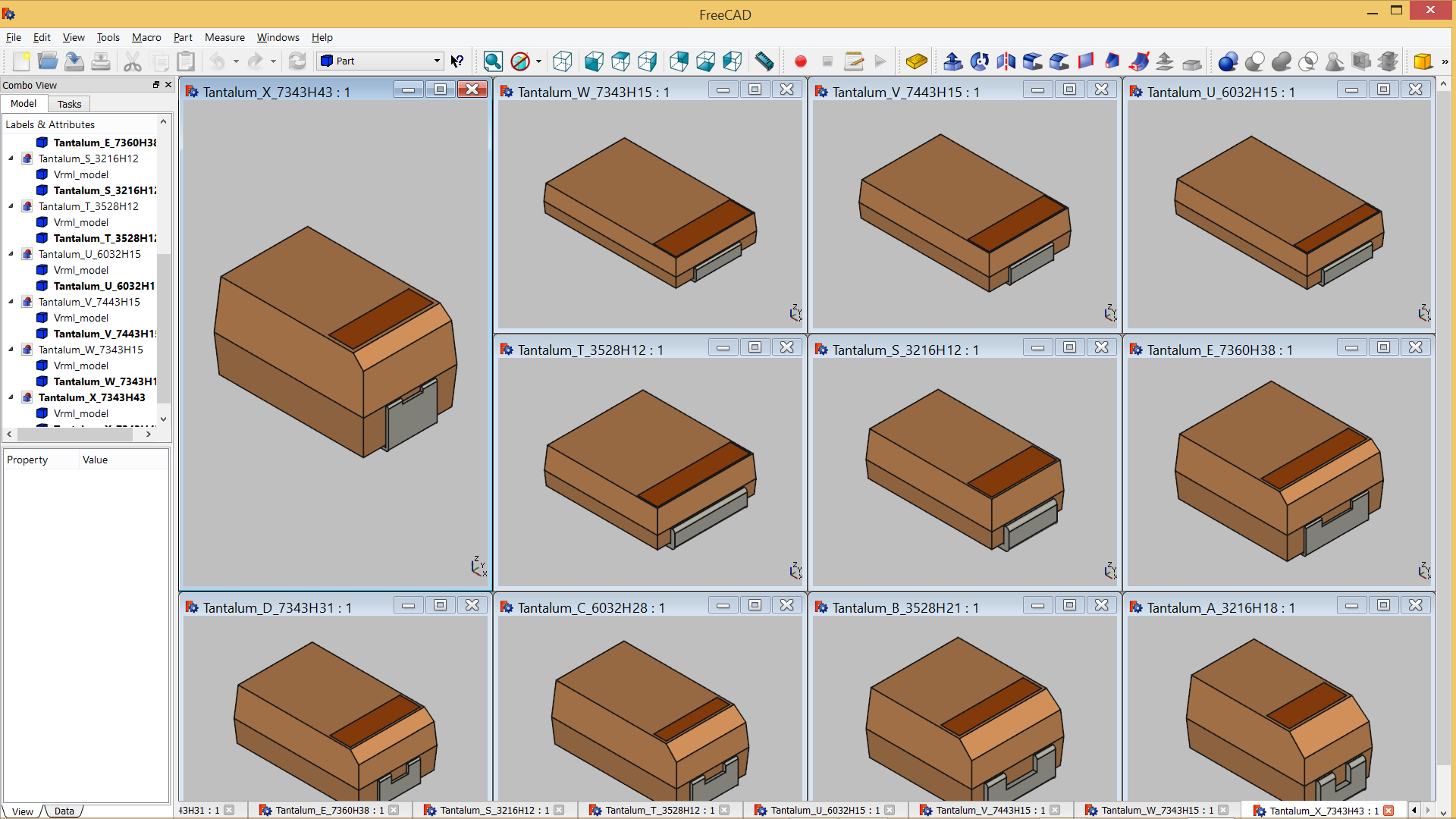
C:\kicad\packages3d_MCAD\Capacitors_Tantalum_SMD.3dshapes
linux/osx
~/packages3d_MCAD/Capacitors_Tantalum_SMD.3dshapes
with all *.wrl and *.step files inside
set your KISYS3DMOD var to e.g. C:\kicad\packages3d_MCAD
It is also possible to just override kicad standard 3D modules,
but consider that an update or a new installation of kicad
will overrite all MCAD models
to set KISYS3DMOD variable in windows open a command prompt in Administrator mode
and digit
SETX KISYS3DMOD C:\kicad\packages3d_MCAD
in ubuntu open a shell bash and digit
export KISYS3DMOD ~\packages3d_MCAD
to export your Kicad board with components to 3D MCAD environment
just use kicad StepUp exporter and kicad StepUp tools at kicad StepUp 3D MCAD exporter
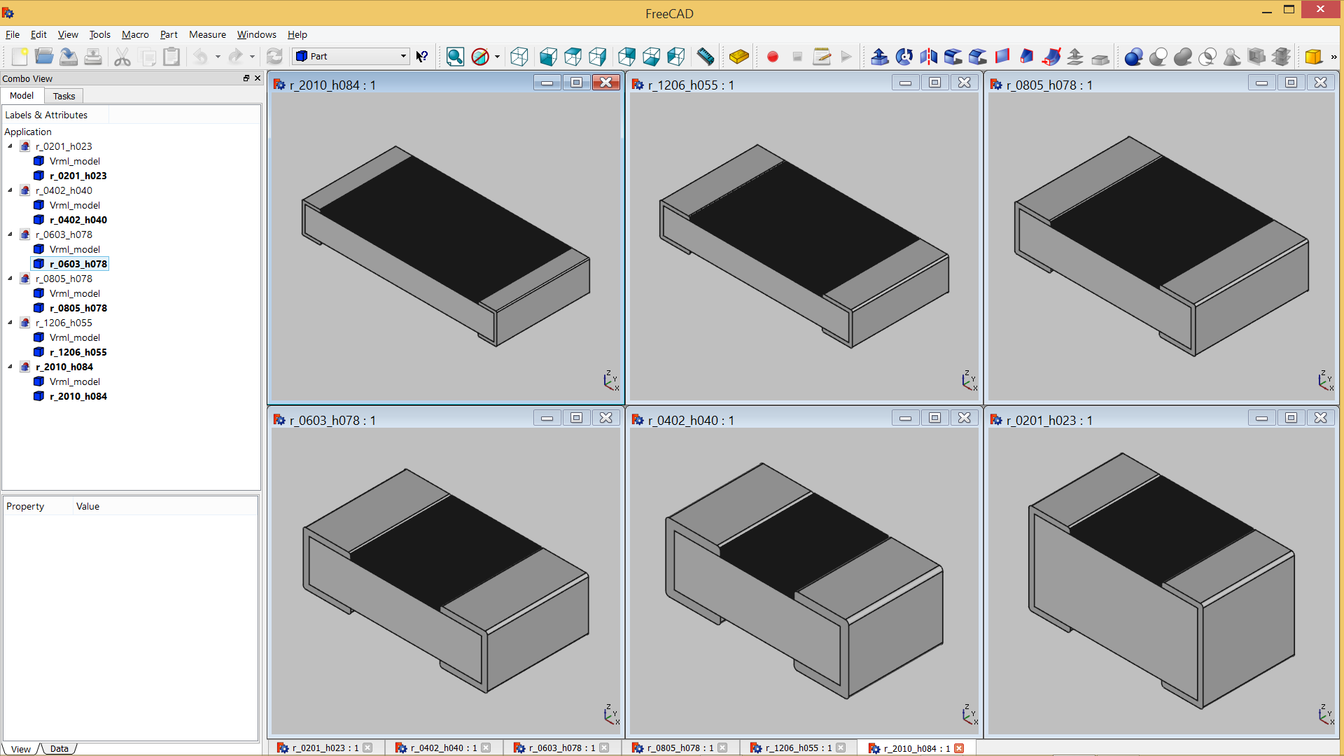
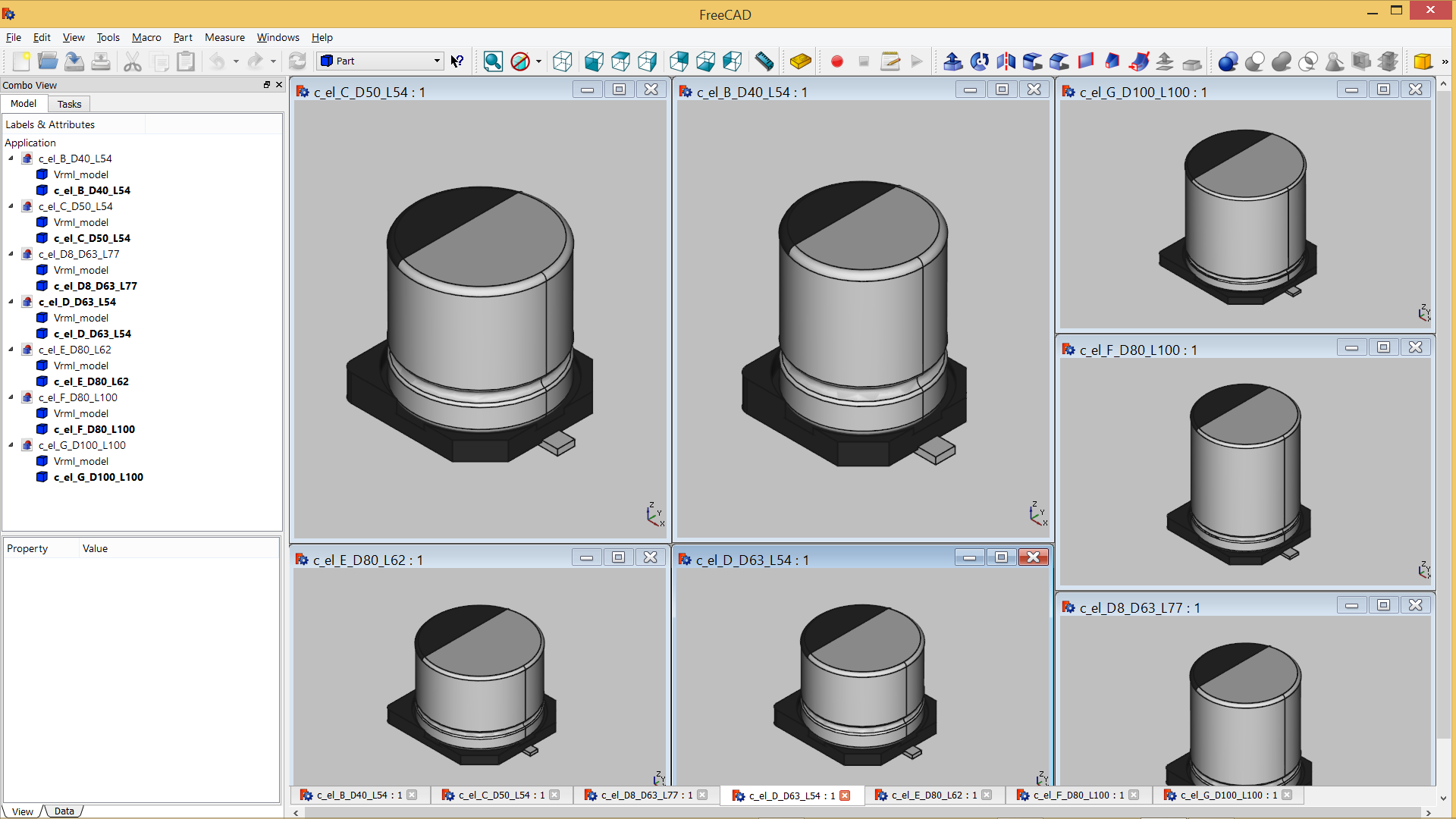
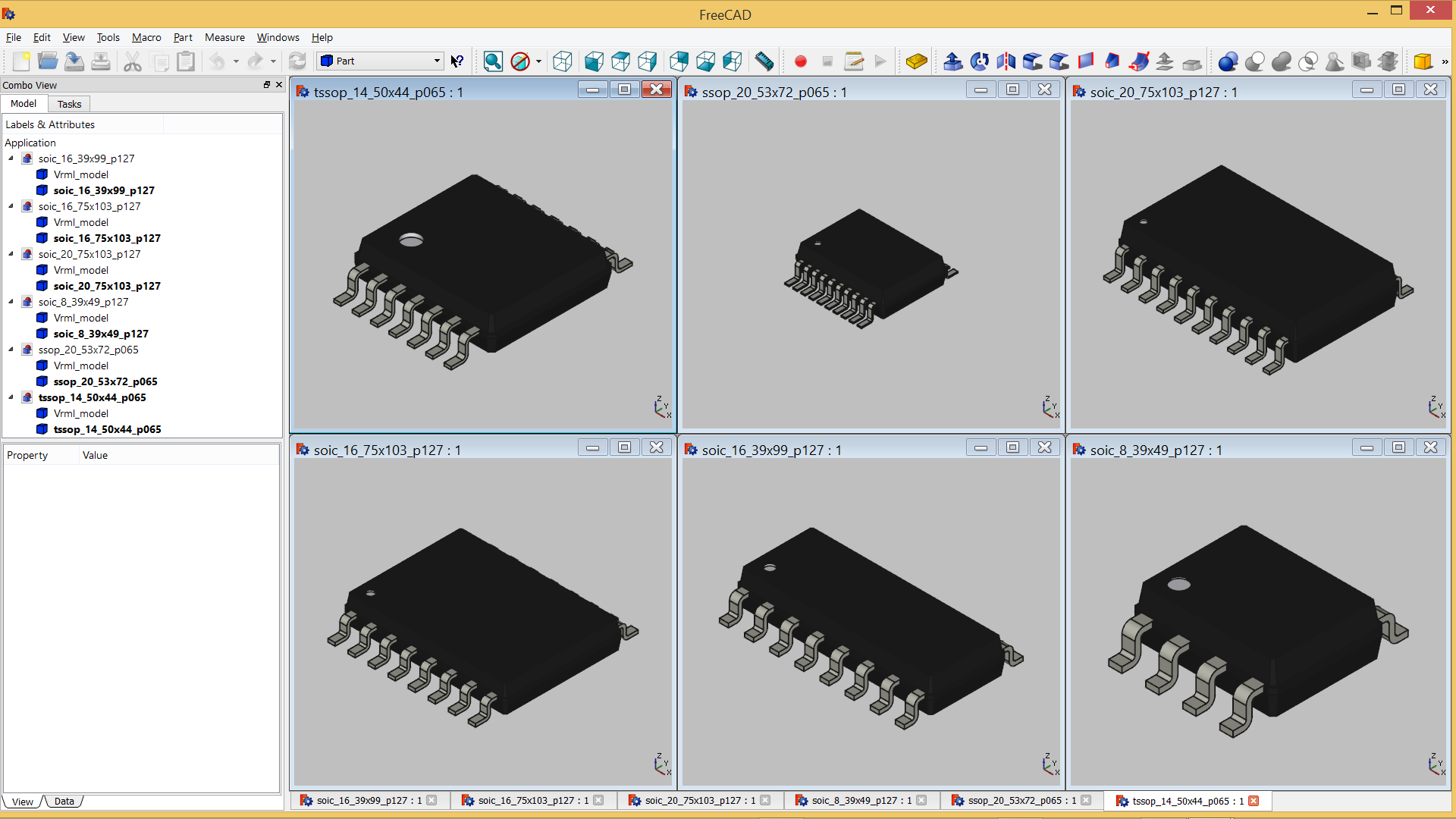
It contains surface mount devices in SOD, SOT and other packages as well as some connectors I have needed for myself (lot’s of versions, not just what’s in the picture above).
The connectors come with labels only atm, but all others are available with and without labels.
The models are oriented so that pin 1 is at the top left most times (I think the DPAK/D2PAK break this rule). The VRML models are scaled by a factor of 0.3937 to be used without scaling in KiCAD. File names are the same for STEP and VRML.
License wise those are all GPLv3+ which is commented into the STEP files - for the VRML files I haven’t added that yet, but will do in due course.
If you find any errors, please send me a message here or on Github.
I already found that I missed the scaling for the PLCC devices and the MELFs (did them manually, vs. all others ran through an automated batch script I wrote for FreeCAD/python that incorporates parts of your multipart scale/conversion macro (*)) and that the rotating of the buzzer model in the original CAD program caused some misalignment of the pins when I check them with my footprint… so yeah, stuff like that.
I’ll upload footprints to those models once I have aligned them to the 3D models.
*)
import FreeCAD
import Import
import FreeCADGui
import ImportGui
import Draft

# export scaled VRML
FreeCAD.newDocument("Unnamed")
FreeCAD.setActiveDocument("Unnamed")
ImportGui.insert(PATH_toStepFiles + FNME_stepfile[:-4] + ".stp","Unnamed")
__objs__=[]
for part in FreeCAD.ActiveDocument.Objects:
    part.ViewObject.DisplayMode = 1 #Shaded
    Draft.scale(part,delta=App.Vector(0.3937,0.3937,0.3937),center=App.Vector(0,0,0),legacy=True)
    __objs__.append(part)
FreeCADGui.export(__objs__,(PATH_toVrmlFiles + FNME_stepfile[:-4] + ".wrl"))
del __objs__
FreeCAD.closeDocument("Unnamed")
The emissive property is indeed supported but the current renderer won’t necessarily make that obvious. The ambient lighting is strange so emissive objects don’t really appear the way you want. In the kicad VRML model repository for example, very many (perhaps most) models define the emissive element as non-zero - everything glows. This is why kicad VRML models generally look awful in other viewers.
In my VRML modeling tool I use more reasonable settings for the material properties and nothing has a non-zero emissive element unless it really emits light. Consistency in the appearance of object is also aided by the use of a specified set of material properties which are re-used by different model generators. For example the black color used for plastic header housings (among other things) is defined in a file “black.mat”:
\# Black plastic (glossy)
\# Copyright 2012 Cirilo Bernardo (cjh.bernardo@gmail.com)
\# License: GPLv.3 http://www.gnu.org/licenses/gpl.html
\#
\# VRML color scheme contributed by Sugeng
In this case the ‘shininess’ value is something I’m not happy with since it results in reflections which are too bright at some angles, but if I wanted to change that I’d simply edit the file and run my model generators to use the updated material spec. In short: define materials if you want to ensure a consistent and good look on your models.
There are some possible natural causes for this type of issues.
It may be related with a bad (== not sufficient) triangulation of the model, or bad triangle orientations/normals (bad model exporting / generation… etc).
Since the render uses per vertex illumination, if you use a very high shininess value, you will see the triangles (== not smooth surfaces), like this:
Using a lower value of shininess (like 1.0 as you are using) should help to diffuse the shine.
Also, remember the specular color is related with shininess. That is the color that is shinned.
Maui - thanks for the FC macro… was really helpful in getting this automated.
Here is my modification/upgrade of it: KiCADinfo_FreeCAD_STEPtoVRML.py (10.6 KB)
Maybe you (or others) can use it or take bits from it.
The script checks a folder for stp files and works with them (add info, convert to vrml) if they are not in a hashfile yet. then a new hashfile is written so only new/changed files have to go through this again.
I still have to add something that adds license info to the vrml files.
Cherry on top would be if the stp file name is of the form “blahblah_T.stp” that the script would stop after setting shaded view and scaling and let me set the transparency for the part that needs it and would then go on it’s merry way… working on that over in the FC forums: http://forum.freecadweb.org/viewtopic.php?f=22&t=13457&p=107639#p107639
@Joan_Sparky
very nice script to add some info on step file
for vrml file you could do something similar to the header
The VRML 2.0 Header and Comments
The first line of the VRML file contains the header #VRML V2.0 utf.
This identifies it as a VRML 2.0 file, as opposed to a VRML 1.0 file, for example. All VRML files must start with this header. The utf keyword refers to the UTF-8 international character set used in the file. The second line starts with the `#’ symbol. This indicates that all the text with follows it, until the end of the line is a comment, and should be ignored by the VRML software. In the example, the comment describes the contents of the scene. http://www.agocg.ac.uk/train/vrml2rep/part1/guide3.htm
I think add different center points for rotation will make things (even more) “complicated to understand” for the user. That should be left to 3dmodel / MCAD editors.
Maybe I can evaluate to add lights. Any good reason for that? (I was thinking do something like that using emissive models as I explained before).
As I agree with some discussions before on 3d-viewer, adding too much options will “confuse” normal users and they will not get good results because they will not full understand or choose the correct values for parameters. So maybe it is better to not expose some o that features, so they will end always with good render results!
in case of big dimensions board, without the ability to move the rotation center it is not possible to view in zooming the peripheral of board …
moreover this is an option very common in any 3d-viewer (e.g. view3dscene, freeWRL, blender etc. have that option)
you just click in a different point and you get the rotation on that (not an option really complicated to be understood, just intuitive)
just aesthetic reason… I was just trying to follow your point of view in 3d-viewer…
As you know, my point of view is more mechanical then aesthetic…
moreover, the MCAD approach I have to 3d-viewer is aligned to what Altium is doing… as per my knowledge in Altium all models are not rendered with ligth properties, just diffuse color
so the only feature I real miss is the ability to move the rotation point, to be able to inspect the edge of board with big dimensions…
ah ok sorry, I thought you were talking in relation of 3d-models transformations…
Lets keep that idea as a wish and see in future… I experience some viewers that have that feature and some are a bit hard (for me) to understand how to use it.
@kammutierspule
so I would add these two items to my whishlist:
intuitive way to move the rotation center of 3D viewer
option to Hide some models (as Altium does for 3d bodies)
Both options would be very useful for 3D enclosure design and MCAD collaboration
May be this is the right timing to ask, because of 3d refactoring work in progress
[quote=“maui, post:15, topic:1763”]
I also miss the ability to move the center point of the rotation view, as is usually available in 3d viewer…[/quote]
Lets keep that idea as a wish and see in future… I experience some viewers that have that feature and some are a bit hard (for me) to understand how to use it.[/quote]
Oh yes, please.
I can deal with different directions of turning the mouse wheel for zooming, I can deal with different behaviors for paning and orbitting… but what I really miss is to be able to have a custom centre point for that.
Inventor: click somewhere ON an object and this becomes your new centre for orbiting/zooming - intuitive
pcbnew: you can zoom with the mouse as centre - intuitive (I find myself cursing at a paintprog lately I use where this doesn’t happen
FreeCAD: sucks, no option to get the centre point defined
KiCAD 3dviewer: sucks, no option to get the centre point defined
If you still take wishes for 3d viewer… a button or keystroke for hiding/showing 3d shapes as the menu is cumbersome for that but it’s the feature I use the most. Absolute fantastic would be on a per footprint basis, but alone a button/keystroke for all of them together would go a long way.


