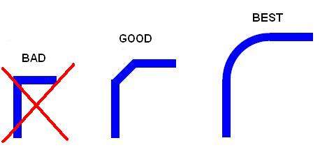
How can I bend a trace like this - refer the trace marked as “best”
http://1.bp.blogspot.com/_Dj6q42y2Hq8/TEwyvQ7RyII/AAAAAAAAAAU/TyZbrPqGzcc/s1600/routing.JPG
3 Likes
Currently you can’t.
1 Like
You can approximate a bend as a series of angled lines. Getting angles other than 0, 45 or 90 on the OpenGL canvas requires diving into menus
There are scripts for spirals, (as multi-segments) that could be modified, but it may also be possible to directly script ARCs - ie run on a loaded design, via Python.
Has anyone tried this ? (script generate of traces directly, not via a file)
The problem with curved tracks created with many line segments is that they do not play nice with the interactive router, that is they do not drag or shove.
Yes, & that s true of many shove routers too, not just KiCad’s
It is the sort of operation that would be done near the end of a design.
On the default canvas there is an option to drag the trace when I right click on the trace.
In OpenGL no such option - could you be kind enough to point out which menu has the angles.
The only menu I could find was the limit track angle to 45 degrees, but that is not allowing me to make a curve.
This is not a answer to your question, but it is some interesting related articles to the subject of PCB corners. I couldn’t put more than 2 links, but on the ultracad site there is also a humorous, sarcastic article about “flying electrons”.
http://www.sigcon.com/Pubs/edn/bigbadbend.htm
1 Like
Thanks for those links. They are saying that even using a small 45 degree segment is overkill below 10GHz
Another argument I’ve heard is that the 90 degree corners can sometimes become over-etched (or is it under-etched? I don’t recall now . . . ) during board fabrication.
Dale
Under/Over etching due to “acid traps” etc are a thing of the distant past, if your fab suggests it might be a problem then it’s time to switch. Most fabs use an alkaline process these days.
I’m always cautious of articles that are nearly 2 decades old. Modern TDR equipment has no problem picking up the reflection from each and every 90 degree corner, even though they are quite small. I’m also skeptical of these kinds of measurements made with only a single active track on a board. 90 degree corners affect the impedance of a trace at the corner due mostly to the change in capacitance. Any reflection caused by this is dependent on rise/fall time, not frequency, and track width. While these reflections are small, in a real circuit on a real board they are added to all of the other noise already present, switching noise, cross talk, ground bounce, etc. Modern high speed CMOS logic (VHC, ALVC) approach 1ns rise/fall times, ECL typically has <100ps rise/fall times.
I’m not trying to say we should avoid 90 degree corners, just that we don’t have to be working with microwave signals for them to be a problem. Most of the time however there is no valid reason to avoid them, it is more of a personal preference.
PS. The general rule of thumb for when 90 degree corners begin to be a problem is when the track width (in mils) is greater than 5x the rise time (in ps).
3 Likes
The only time 90 degree corners are likely is when there is a layer change and a via. The impedance discontinuity of the via is much worse than track bend geometry will cause
I’m not sure what you mean by that, if you are referring to the corner created by the via itself. perpendicular to the board surface, well as corners go that is insignificant.
Nonsense! This is just another myth that has perpetuated on forums like this for years. Where is the evidence to support this claim. Sure, impedance calculators that claim to calculate the theoretical impedance of vias almost always indicate the impedance to be much lower than a track. There has been at least one TDR study, like the studies for square corners, that show that’s not the case. Again you need extremely fast rise times before vias have any detrimental impact on signal integrity. The return path for the signal is of more importance than the via itself. In situations where you really must have a via with tightly controlled impedance then you can always create one. Like square corners, most of the time there is no valid reason to avoid vias.
Most PCB Cad use 45 degree segments automatically when a track changes direction.
I do see right angle when an autorouted board has two layers, one favouring N-S and the other E-W
If you are talking about a horizontal track on one layer and a vertical track on another connected by a via, that is not the same as a track with a right angle corner.
My point. It’s a long time since I saw a cad system lay out a right angle trace on a single layer by accident
What I do for arced traces:
- In your layout (Pcbnew), use the graphic arc tool to make your trace with a graphical line, pretending to connect two straight traces or two pads.
- I then view the parameters of the arc and note down all dimensions like angles and position.
- In footprint editor, make a new footprint with a graphical arc with the same exact parameters and change it’s layer to top/bottom copper.
- Import the footprint into Pcbnew. Now, you could either edit the footprint beforehand with SMD pads 1 and 2 in both ends, but then you have to include it as a part in your schematic/netlist. What I do instead is just to lay down the new arced footprint where it should go, and route a thinner “invisible” trace behind it (this will be somewhat staggered, but hidden), leaving the arced footprint unconnected.
1 Like
By accident?
We don’t see many tracks with right angle corners because everyone has been brainwashed into believing they are a bad design practice. Only “noobs” who haven’t been brainwashed yet or those who know better ever use right angle corners these days. But every EDA package I have used allows 90 degree corners, some have options to disable them or flag them as DRC errors. DesignSpark PCB, PCB123, Altium, OrCad, and of course KiCAD, all allow right angle corners. Some auto-routers route with right angle corners and then optionally make additional passes at the end replacing them with 45s.
1 Like
Ignoring questionable impedance effects, 90 degree bends make tracks longer and therefore waste board area, so 45 degree segments do make sense
1 Like