Well I have finally managed to successfully create my very 1st 3D model for kicad using Wings3d.
It’s a 3d model of the Pololu Drv8825 stepper driver board.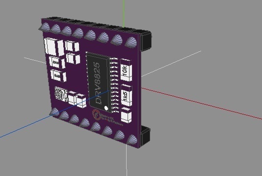
I am currently trying to layout the DIY version of the AstroEQ telescope controller and I wanted to use this in the 3d view of the board so it looks bettter. I will post a completed pic of the board when its finished
Andy
1 Like
Hi Andy,
that looks cool 
do you entirely designed it in wings3d?
i think you could have done this in KiCad itself - just rebuild the PCB and export the 3D-Data -
i have never get the motivation to learn wings3d…
i use blender and FreeCad to design my models..
and for the process to convert so that kicad finally can read it i use wings3d 
example of the HopeRF RFM69 modul (as THT variant):
Blender Render:
KiCad 3D Display:
sometimes i get a bit crazy about details for example at this smd crystal - its just to much fun to do this rounded edges and things with FreeCad:
here is my ‘Workflow’:
3D Model for KiCad Footprints:
Here is a working process to generate 3D *.wrl Files for KiCad PCBNew 3D-Viewer.
Tested with KiCad Versions:
-
Application: KiCad
Version: (2013-07-07 BZR 4022)-stable
Build: wxWidgets 2.9.4 (wchar_t,compiler with C++ ABI 1002,GCC 4.7.2,wx containers,compatible with 2.8)
Platform: Windows 7 (build 7601, Service Pack 1), 64-bit edition, 64 bit, Little endian, wxMSW
Boost version: 1.53.0
Options: USE_PCBNEW_NANOMETRES=ON
         KICAD_GOST=OFF
         USE_WX_GRAPHICS_CONTEXT=OFF
         USE_WX_OVERLAY=OFF
         KICAD_SCRIPTING=OFF
         KICAD_SCRIPTING_MODULES=OFF
         KICAD_SCRIPTING_WXPYTHON=OFF
-
Application: kicad
Version: (2014-12-04 BZR 5312)-product Release build
wxWidgets: Version 3.0.0 (debug,wchar_t,compiler with C++ ABI 1002,GCC 4.8.2,wx containers,compatible with 2.8)
Platform: Windows 7 (build 7601, Service Pack 1), 64-bit edition, 64 bit, Little endian, wxMSW
Boost version: 1.54.0
         USE_WX_GRAPHICS_CONTEXT=OFF
         USE_WX_OVERLAY=OFF
         KICAD_SCRIPTING=ON
         KICAD_SCRIPTING_MODULES=ON
         KICAD_SCRIPTING_WXPYTHON=ON
         USE_FP_LIB_TABLE=HARD_CODED_ON
         BUILD_GITHUB_PLUGIN=ON
FreeCad is used to generate Solid accurate Models
out of the informations from the datasheets.
For Packages with repeating Patterns(like Pins or Pads on a DIP or SOIC, ...) Blender comes with a wonderfull array-modifier.
so its easy to generate only one pin in FreeCad (accurate measurements) and generate the pattern with the modifier in blender.
Additional it is easy to manage the materials in blender more easily.
i have tested the blender wrl export and it did not work in KiCad.
the Wings3D export is working nicely - its a extra step but works ;-)
if some one has the time / knowledge to implement / extend the Blender WRL exporter to fit the KiCad format it would make it faster...
this could be done as python script.
generate model in FreeCad:
FreeCad:
    use orig. mm
    export as *__FreeCADExport.wrl
Blender:
import *__FreeCADExport.wrl
axis_forward = ‘Y’
axis_up = ‘Z’
clean up import:
search all not needed objects and delete.
rename used objects and also rename meshes.
check materials and rename
Ambient=1
Specular>=0.5
export from blender as *__BlenderExport.obj
options see Blender export
generate model in Blender:
Blender:
    use orig. mm
    export from blender as *__BlenderExport.obj
        'blender2wings3d'
        op.use_selection = False
        op.use_animation = False
        op.use_mesh_modifiers = True
        op.use_edges = True
        op.use_smooth_groups = False
        op.use_normals = False
        op.use_uvs = True
        op.use_materials = True
        op.use_triangles = False
        op.use_nurbs = False
        op.use_vertex_groups = False
        op.use_blen_objects = True
        op.group_by_object = False
        op.group_by_material = False
        op.keep_vertex_order = False
        op.axis_forward = '-Y'
        op.axis_up = 'Z'
        op.global_scale = 393.6
        op.path_mode = 'AUTO'
Convert to KiCad PCBNew '*.wrl file'
Wings3D:
    import *__BlenderExport.obj
    export as *.wrl
// Needed for KiCad Versions <= (2014-12-04 BZR 5312)-product Release build
Text Editor (Notepad++):
open *.wrl
search for ‘ambientIntensity 0.0’
replace with ‘ambientIntensity 1.0’
KiCad PCBNew
load *.wrl as 3D shape
Scale=1
Shape Offset = 0;
Rotation=0
i have documented this ‘workflow’ just that i can remember what steps to take..
it is relative complicated - but i like the software involved.. so i have fun doing it this way…
sunny greetings
stefan
2 Likes
I used 3d files that I had already downloaded then i just used the wings3d merge option to add the parts i needed. I am in the process of learning to build my parts from scratch.
I like the look of your designs too. Thanks for your workflow. I’ll take a look at it myself
I have an old 3D modeling project for kicad on SourceForge: kicad3dmodels.sourceforge.net
These tools are currently being proposed for merging with kicad (but that might take a few months).
The example batch scripts currently create over 6000 models.
Here is my workflow for Autodesk Inventor to get final 3D models in KiCAD that are scaled and in the right orientation (= flat on pcb, only z-rotation needed). It seems convoluted, but it’s the tool I can work in best and highest speed - maybe somebody finds this useful:
- creating the part in original size in Inventor
- making a new file and importing the created part as derived part > setting the scale factor to 0.393 (don’t ask me why, it’s ‘=1 / 25.4’ and seems to be just right)
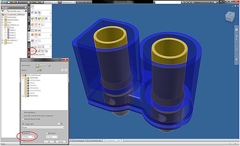
- exporting the result as STEP
- importing the STEP part in FreeCAD, opening the Data tab and putting in Angle 90’ and changing the axis values x = 1.0 and z = 0.0
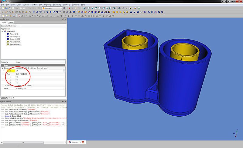
- exporting it to VRML and then adding the part in the footprint editor in KiCAD
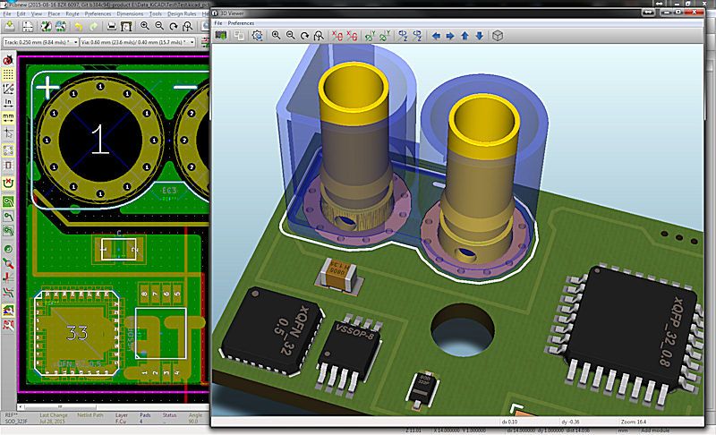
The EC3 connector did cause a bit more work as I wanted the housing to be transparent once in KiCAD.
To get this done I derived the housing and connectors as single objects, exported them together and imported them into FreeCAD… as one can see on the screenshot they became separate parts then and for the housing I could adjust the translucency and this setting did make it through to KiCAD as one can see in the 3D viewer.
Use case for an EC3 connector in a PCB?
My dad wanted that for his battery pack… but I guess any rc-pilot could use it, it’s attached. KiCAD_EC3-connector_footprint&3Dmodel.zip (328.6 KB)


