KiCad and Spice simulations

I am relatively new to KiCad, having created and ordered my first PCB designed using KiCad only a week ago!

As a hobbyist, up until now I have been using LT Spice for SPICE simulation. Now that I am using KiCad for PBC layout, this means having to design and test the schematic in LT Spice and then re-drawing it a second time in Eeschema in order to be able proceed to the PCB design stage. It therefore seemed like a good idea to experiment with the KiCad integrated ngspice simulator as that way the schematic would only have to be drawn once. I am presently running KiCad 5.0.0 on Linux.

I was able to successfully test the RC Ladder example in the tutorial here so it seems that the simulator is working:
http://ngspice.sourceforge.net/ngspice-eeschema.html

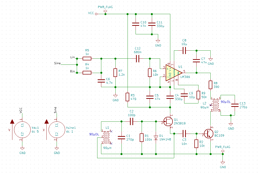
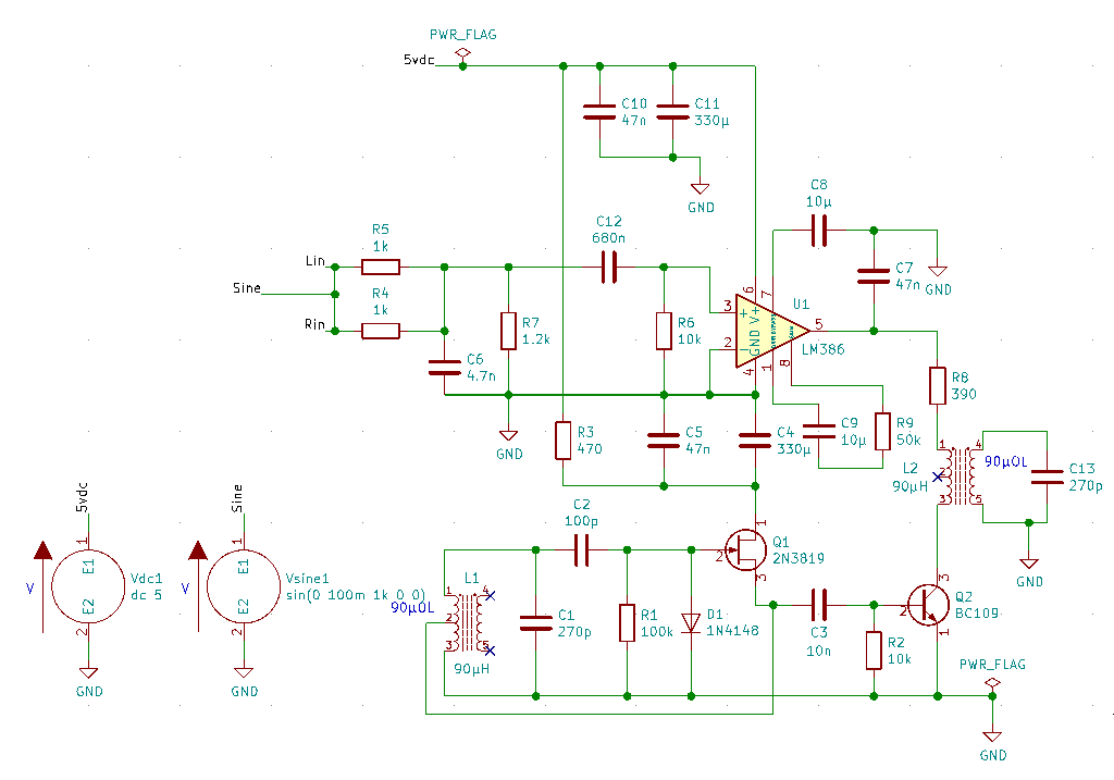
The first thing that somewhat surprised when I started drawing my own schematic (which has already been tested successfully in LT Spice) was that there was not model for a 1N4148 diode or a BC109 transistor. Ok, so spice models can be found online and I already had some of them so I found a standard.bjt library which included the BC109, I copied the 1N4148 model from LT Spice, and used the third party LM386 model that I already had downloaded for the existing project in LT Spice. For the LM386, I made sure to set up the alternative Spice Node Sequence to match the model. Having got rid of any errors relating to model configuration I then got this:

Circuit: KiCad schematic
Original line no.: 1, new internal line no.: 4:
Undefined number [ONSEMI]
Original line no.: 1, new internal line no.: 4:
Cannot compute substitute
Original line no.: 57, new internal line no.: 125:
Undefined number [PHILIPS]
Original line no.: 57, new internal line no.: 125:
Expression err: philips)
Original line no.: 57, new internal line no.: 125:
Cannot compute substitute
Copies=392 Evals=395 Placeholders=3 Symbols=7 Errors=5
Numparam expansion errors: Problem with input file.
Error: ngspice.dll cannot recover and awaits to be detached
Note: canā€™t find init file.


** ngspice-27 shared library
** Creation Date: Mon Dec 11 08:26:09 UTC 2017


Error: there arenā€™t any circuits loaded.

At present I am doing a transient simulation and setting up the parameters in Settings in the simulator GUI, time step 1u, final time 100msec. Iā€™m told these line numbers relate to the ā€˜internalā€™ parsed file that is passed to ngspice. In an attempt to debug this further and show this listing, I added the following to the schematic text:

+PSPICE
.control
listing
.endc

Unfortunately, it made no difference.
Not sure how to proceed from here, so any help would be appreciated.

Due to practical differences, you are still better off simulating with a schematic dedicated to simulation.

Iā€™m always surprised that people are surprised that KiCad does not have a comprehensive library of part data. Who exactly do you think is going to provide of all that?

Start with basic examples from the documentation for KiCad and ngspice, then work up to more complex examples, and finally simulate parts of your own schematic. Same with any tool really.

1 Like

You are using ngspice-27.
You are experiencing some cryptic error messages complaining about PHILIPS or ONSEMI.
That hints to your using device models that are incompatible with ngspice-27 (typically are written according to PSPICE rules, just another simulator, usable with LTSPICE, but not with ngspice-26 or -27).

I would see two ways to dealing with this problem:
You might make the models compatible. It may help that you simply delete the entries mfg=PHILIPS etc in your model files. If this does not help, you may publish the links where you got the models, and we can have a look.

The better, but more tedious way would be to install ngspice-28. This has a PSPICE compatibility mode being enabled by creating a .spiceinit file and adding the lines

* user provided init file
set ngbehavior=ps

as described in the tutorial.

1 Like

bobc, I tend to agree that the requirements for simulation will differ to those for PCB layout. For example, the latter may require connectors, switches and other parts to be located on the board which are of no relevance to the simulation. In fact, my project will include a small module board for which I have drawn a footprint, but which I cannot simulate in SPICE, but which will need to be represented in the final schematic. For this reason I was trying to set up two schematic sheets within my project. I took me a while to figure out how to clone the schematic at a specific point on to a second sheet, which in the end I did by copying the original SPICE ready schematic file and the appending the renamed copy to the project. I intend to use the copy for SPICE simulation, and continue to develop the original for the PCB layout.

I also take your point about the library of parts, but even the devs must have been working with something to test things. I was not expecting a full library of parts, but equally was not expecting to have no semiconductor parts at all. Even some basic well known semiconductors would have been useful to start with. As I said though, it easy enough to find them is you search online, although it seems that using third party models has its own issues.

holdger, thanks for clarifying things for me. This now makes sense. Although I have no idea which version of the ngspice library I have, I know it was just installed automatically when I installed the stable release of KiCad 5.0.0 from their ppa repository. Dpkg gives me ā€˜0.1-2~201712110820+2e5be8d~ubuntu18.04.1ā€™ as the version which indicates the date of release as December last year and which is before ngspice-28 was released so its clearly an older version. If the PSPICE compatibility mode was not yet present in earlier versions then the .spiceinit file would not be relevant and have no effect on the current version I have installed. Thanks also for explaining the purpose of this file as I had wondered whether ā€˜psā€™ in the second line was short for PSPICE and hence relating to enabling PSPICE compatibility.

I did do a grep search on PHILIPS and ONSEMI on files in the project directory and found that the standard.bjt file that I am using contains the parameter mfg=PHILIPS on a number of transistor models that are included. I had thought of removing that parameter but wanā€™t sure. The file was downloaded from here:
https://groups.yahoo.com/neo/groups/LTspice/files/%20Lib/%20cmp/Updated%20BJT/
I didnā€™t get a hit for ONSEMI, so Iā€™m still not sure where it is picking that up from.

I tried and was able to compile the ngspice-28 shared library using the following configure flags:

./configure --enable-xspice --enable-cider --enable-openmp --disable-debug --with-ngshared

For the configure script to complete, I had to additionally install the package libxaw7-dev.

The problem I have now is that when I try to remove the existing libngspice-kicad package so that I can install the compiled version 28, the system also wants to remove the kicad package.

BTW, my apologies, but I donā€™t see how to include quotes on this forum, otherwise I would have made use of that facility.

This was listed in the ngspice error message.

Unfortunately I cannot help with the Linux installation, but see Ngspice-28 for KiCad, offered by mifi.

Mark the text with left mouse button, a button ā€˜quoteā€™ appears, left click onto the button, marked text moves to your text input box.

Doh! Should have spotted that!

Thanks for that link. I did actually find that thread myself in the meantime so I will experiment with that info on my test virtual machine later.

UPDATE: I extracted the BC109 definition from standard.bjt and did some further testing. It seems that it is necessary to remove mfg=PHILIPS from the model. I also found mfg=OnSemi in the model for the 1N4148. I found I also had to remove type=silicon from this model. This got me past the line errors, but there are still plenty of
'unrecognized parameter (nk) - ignored and other similar messages present (vceo, vpk, iave, icrating to name a few ignored parameters). Maybe the ngspice-28 PSPICE compatibility will clean that up, but I presume since they are ignored it shouldnā€™t be an issue?

The other issue seems to be my subckt definitions of the RF choke:

Error on line 0 :
k.xl2.k1 l.xl2.l1 l.xl2.l2 l3 1
unknown parameter (l3)
Error on line 0 :
k.xl1.k1 l.xl1.l1 l.xl1.l2 l3 1
unknown parameter (l3)

This is my definition, which I based on other examples:

* Subcircuit for RF choke 90ĀµOL
* CONNECTIONS:  PRIMARY 1
*               | PRIMARY2
*               | | PRIMARY3
*               | | | SECONDARY 1
*               | | | | SECONDARY 2
*               | | | | |
.SUBCKT	L90UOL	1 2 3 4 5
L1	1	2	68.66E6
L2	2	3	21.34E6
L3	4	5	6.85E6
K1	L1 L2 L3 1
.ENDS

Iā€™m not sure whether the K1 statement should be there, but somehow the 3 coils need to be inductively coupled. I have two instances of this device on my schematic (L1 and L2), so in the context of the schematic ā€˜L3ā€™ would indeed be invalid, but I thought that the statement would be evaluated in the context of the subckt.

Thanks for the pointer on including quotes.

Coupling is possible between two inductors only (ngspice-28 manual, p. 78).

See example ngspice\examples\inductive-systems\positive-definite-2.cir in your ngspice-28 tarball for coupling of three inductors.

Ah! Iā€™m thinking in LT Spice terms!

I have modified it as follows:

* Subcircuit for RF choke 90ĀµOL
* John Chajecki, Rev 1.00, 06/11/2018
* CONNECTIONS:  PRIMARY 1
*               | PRIMARY2
*               | | PRIMARY3
*               | | | SECONDARY 1
*               | | | | SECONDARY 2
*               | | | | |
.subckt	l90uOL	1 2 3 4 5
L1	1	2	68.66E6
L2	2	3	21.34E6
L3	4	5	6.85E6
K12 L1 L2 0.95
K13 L1 L3 0.95
K23 L2 L3 0.95
.ends

It is still simplistic but it works in as much as the error is gone.

Which leads me on to this. It seems that spice does not like having nc points on the schematic regardless of whether they are marked with an nc flag or not. In one scenario, the center tap of the tx is not used, in the other, the entire secondary is not used. I have uploaded an image of the circuit to: http://jchaj.trancell.org/images/spice/circuit.png. I tried adding the dc resistance of the windings to the model, but spice then complained that the resistance was too low and changed it to 1mOhm.

I also have an issue with the NJT model type not being recognized by KiCad so I may need to upgrade to the nightly version as I understand that the JFET recognition is fixed there.

OUTPUT:
Warning: vsine1: no DC value, transient time 0 value used
Warning: singular matrix: check nodes nc_03 and nc_03
Note: Starting dynamic gmin stepping
Trying gmin = 1.0000E-03 Warning: singular matrix: check nodes nc_03 and nc_03
Warning: Further gmin increment
Trying gmin = 5.6234E-03 Warning: singular matrix: check nodes nc_03 and nc_03
Warning: Further gmin increment
Trying gmin = 8.6596E-03 Warning: singular matrix: check nodes nc_03 and nc_03
Warning: Further gmin increment
Trying gmin = 9.6466E-03 Warning: singular matrix: check nodes nc_03 and nc_03
Warning: Further gmin increment
Trying gmin = 9.9105E-03 Warning: singular matrix: check nodes nc_03 and nc_03
Warning: Further gmin increment
Trying gmin = 9.9775E-03 Warning: singular matrix: check nodes nc_03 and nc_03
Warning: Further gmin increment
Trying gmin = 9.9944E-03 Warning: singular matrix: check nodes nc_03 and nc_03
Warning: Further gmin increment
Trying gmin = 9.9986E-03 Warning: singular matrix: check nodes nc_03 and nc_03
Warning: Further gmin increment
Trying gmin = 9.9996E-03 Warning: singular matrix: check nodes nc_03 and nc_03
Warning: Last gmin step failed
Warning: singular matrix: check nodes nc_03 and nc_03
Warning: Dynamic gmin stepping failed
Note: Starting source stepping
Supplies reduced to 0.0000% Warning: singular matrix: check nodes nc_03 and nc_03
Trying gmin = 1.0000E-02 Warning: singular matrix: check nodes nc_03 and nc_03
Warning: gmin step failed
Warning: source stepping failed
Transient solution failed -

Finally got rid of errors relating to my model with a definition like this:

.param Lp1=81.855uH Lp2=8.145uH Ls=1uH
.param Rp1=2.02 Rp2=0.64 Rs=0.18
* CONNECTIONS:  PRIMARY 1
*               | PRIMARY2
*               | | PRIMARY3
*               | | | SECONDARY 1
*               | | | | SECONDARY 2
*               | | | | |
.subckt	l90uOL	1 2 3 4 5   
* Primaries
R11 1 11  {Rp1}
L11 11 2  {Lp1}
R12 2 12  {Rp2}
L12 12 3  {Lp2}
* Secondary
R21 4 14  {Rs}
R22 14 0  10G
L21 14 5  {Ls}
* Coupling (ferrite core)
K12 L11 L12 0.95
K13 L11 L21 0.95
K23 L12 L21 0.95
.ends
  • Note: R22 prevents singular node error on node 14

I have now got to a point where the simulation runs, but, it seems that my voltage source is not working. In LT Spice this was a simple matter of attaching a label with the same ID to the voltage source and the net which, in effect, connected them. In KiCad there is a confusing array of labels, power ports, power flags and even different symbols for ground. It seems that the rules for the ERC check differ from what is required for the SPICE simulation. Having spent literally hours trawling through discussions on the subject and trying various things I still none the wiser as to why my power source is showing only nanovolts on the graphic in the simulator.

At present I have a power flag on the 5v rail in my schematic, and the VSOURCE is connected using local labels. The power source is configured as dc 5 (I also tried adding ac 0), but the simulation shows 0. Iā€™m totally baffled. How difficult can this be? By contrast, there seems to be no issue with the sinewave source which is also connected by a local label and seems to work just fine. Obviously I am making some stupid mistake somewhere but I canā€™t see whatā€¦

My circuit

The ground symbol for ngspice needs to have a net of ā€œ0ā€ but KiCad uses ā€œGNDā€. One of the many reasons why I suggest creating a different schematic for simulation, and also starting with simple examples to verify you are on the right track.

1 Like

I tried that - i.e. changing all the GND power ports to 0 but this did not make any difference. Iā€™m still not getting any DC power to the circuit. Tried also connecting with global labels, power ports and local labels, with power flag and without. No combination seems to work for DC.

If you canā€™t see the forest for the trees, you can either wander around indefinitely or try looking in a smaller forest.

1 Like

Well I knew it would turn out to be something stupid!
It turns out that for the 5v source, the Spice_Netlist_Enabled was set to N!
Setting it to Y brought sanity back to the project!
No idea why, how or when it got set to N but, in my defence, in the nightly release version the layout of the symbol properties dialog has been re-designed and this parameter, being the last in the list does not appear until you scroll down a bit. Of course, this would have been impossible for anyone to spot from the circuit diagram alone, but I appreciate the feedback I have received.

Anyway the simulation now works at last!

2 Likes

I came to KiCad for the exact same reason as @WaveyDipole, Here you seem to suggest that KiCad is not ready for solid Spice simulation. What is the official position?

KiCad is ready for spice. However if you want to create a pcb then you will need to have a special schematic for simulations.

The same schematic can not be used to make both a simulation and a pcb (at least not cleanly)

2 Likes