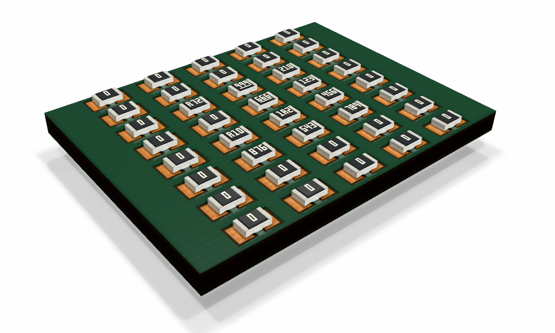
I would like to share with you a new 3D library I am creating specific to be used with KiCad 5.
My main propose with the library is to create components with its values (eg: resistors values digits / colors).
There is a generic 3D CAD model file (with no values) for CAD proposes for each component type and there are the variant values in WRL for use with KiCad 3DViewer.
Each value WRL file is very small (~500 bytes) as it uses an ‘include’ directive (with transformations) now supported on new KiCad 3DViewer, this way it is possible to generate and store thousands of files with the values.
The project is shared at
where you can find the source code and pre-generated zip files.
I will add more components once in a while…
Let me know if you have a specific request and share your 3D renders with community!
@kammutierspule does each “instance” of the resistor get saved with its own file? Ideally, there would be ONE master file and KiCAD could programatically generate temporary models as needed (based on the value of the component). If I understand your libs correctly, each model needs to be generated individually?
These look very good. Is the VRML based in any way on the FreeCAD/STEP model or do you essentially build two sets of models? One other question on the resistor leads: can you change the pitch and can you change the orientation (vertical/horizontal) on the resistors?
The software is generating all WRL file variants, that is thousands files. yes individually.
You can already get the files generated in the zip files eg, here:
But, each file is very minimal because it is calling, as you said a “ONE master file” (actually the main body + the variant values/colors)
For example the R102.wrl (1K resistor) has this code:
So users just need to add the correct WRL file to each footprint as normally (manually…)
Integrating this in KiCad (3DViewer) automatically will be possible but I think it may get confused (as it will need more options and changes on the file format?)
The 3D CAD model is present. There are the FreeCAD + STEP exported for each component type (eg: 0805, axial resistor). The CAD model does not have any values (i.e: the digits or the color rings on the case of the resistors).
The STEP can be used in KiCad v5 (or other SW) for CAD proposes, but you will not get the values.
The WRL file adds the values/colors and the Materials (for a better rendering).
The (main / master) models were designed (just once) in FreeCAD and exported to VRML using @maui StepUp tool. I made some manual cleanup and adjustments (special materials).
So the original (without values) FreeCAD / STEP models are present.
What do you mean by pitch? In the case of the Axial THT resistor? As my FreeCAD models are not parametric, I will need to manual create a new model. That also means I am conditioned by my time and FreeCAD skills to generate new component models (also the variants eg: 0603 … 1206… etc)
My propose was to keep the master model always as on a CAD format. (i.e: it would be easier to play in VRML as you did on your script tool… but it will not get the CAD models back :/)
My library also differs from the parametric library by @maui and @Joan_Sparky
It works, but for the propose of the lib I am creating, only if you have an idea of ICs that need some automated lettering.
If you are thinking on specific ICs and you want to have add some reference or just for eyecandy proposes, that is already possible to do with KiCad v4.
You can use Inkscape -> FreeCAD -> StepUp -> Add VRML file to footprint as the normal way and get this result:
You know, it might be more straightforward to have a single sided plane (only one, 2 trinagles, 4 points) defined in the models where a texture is being created on the fly that contains the %VAL field.
I know for ICs that won’t be ‘realistic’, but I leave it to your imagination to get that full chip info incorporated into the schematic fields as I’d really like to be able to access some of those with the footprints - which would be more important to me.
The other way is to have 1 model for each and every IC out there… or giving the user a very simple way of doing this. But as I said, it actually might be more straightforward then to implement it as a on-the-fly texture on a single plane - so there is one generic housing shape with a text-plane and on the fly it get’s ‘special’.
This is the way to do it, if it is to receive any serious consideration. Having “thousands of models” is great from a “look how many models I have” point of view, but not that useful in terms of making use of them.
Code that looks at the value of the part and applies a texture / color on-the-fly would be awesome.
That way you can have your banded THT resistors, numbered SMD resistors, ICs with names on them, colored LEDs, etc.
i.e. for 0805 resistors, you will have just one single 3D model, but different values on top, coming from their part values
Using this approach it would be possible to use just STEP models and having also text over them or WRL models for a better 3D raytracing and a corrispondent single 3D model in STEP for MCAD conversion using StepUp
WRL are also allowing transparency on 3D viewer which is useful for example when designing pcb with enclosure
Moreover, imo, nice rendering are useful not only for eye-candy, but also for promoting products…
it depends I prefer to toggle all (having all values)… but it would possible to mix visibility of Values as set in pcbnew in AND with the flag for 3D viewer; so there will be no need to add more fields on the sw for each model
EDIT:
And I remember that I had an option to display values or references, so to easily have an image of the mounting assembly with references or values
yes it would be simpler for the user (more flexible … logos…etc)
But I didn’t had time to implement textures on the 3DViewer It will not be that so easy (special implementing it on Raytracing, because of the transparencies)
Textures some times look better (if proper implemented) but on other cases they will look bad (lack of resolution or too much blur)
Hehe, no problem mate. I just threw it out there as the work involved with creating all those special 3D meshes vs. the work doing something more fundamental that would enable a lot more options and freedom down the road might be ‘similar’ from an man-hour-point-of-view.
This would be possible but is not that easy as you may think, there are some situations:
It would need to be an integrated solution on the KiCad source code (3D models embedded or as resources of the software, not the library)
The kicad ‘Value’ field is actually a reference of the part, some people (like me) are using the ‘Value’ as the unique reference of the part (may be the manufacture code, or internal code) so that will be not possible to extract (by guessing) that from footprints. (unless you create specific fields for this propose)
The easiest way I can think to implement this will be in the UI dialog where you add the model files, you will need to add other options to “add stuff that it is not a model file”, that way user will specific access a dialog to configure an automatic generated model (eg: user will make a choice to add a EIA 0805 resistor with a value xxx ). So that generator will be able to create a specific 3D based on the user options and choices (placing the text on the right place, or the color rings…etc)
This may need a long time of discussion in the development mailing list, special if any changes would be need on the file formats.
I have no idea (depending how much component model I create)
but I know that in a 2…3 day time I learned how to model using FreeCAD for the first time (and first 3D CAD software I used ever), created 2 models, created 10 numbers + one letter, developed the software to generate the WRML files and created / shared the project online.
Implement textures will take a much longer time. I will only know if I start it or someone… one day…
Seems like a lot of effort for some eye candy. I wouldn’t want KiCad to become slow and bloated with 3D modelling features. The 3d viewer is already slowing down significantly, I turn most of the options off. What is needed is a quick 3D view and accurate MCAD export, the rest seems to be doing stuff for the sake of it.
I think if people want “advertising shoot quality renders” it is best done in a CAD tool outside of KiCad. I am quite certain no customer will care if the resistor bands are not the right colours. That is just an engineer’s OCD thing.


 It will not be that so easy (special implementing it on Raytracing, because of the transparencies)