This is mostly theoretical, as KiCad does not support arbitrary “negatively defined” items to be defined by their users. It’s just some stubborn misconception.
First:
I had a look at the (unofficial source) https://www2.pv.infn.it/~servel/rc_images/gerber_rs274xrevd_e.pdf
And from that file:
Extended Gerber Format, which is also called RS-274X, provides enhancements that handle polygon fill codes, positive/negative image compositing, and custom apertures,
So it does support negative features, and apparently does so in several ways for different sorts of features (flash codes, whole images). In the header(line 6) of the solder mask file I used below is a line that (probably) specifies the whole file is to be inverted:
%TF.FilePolarity,Negative*%
Sure, if you just define gerbers as being “negative”, then file size does not change. However, the idea about the ability to use negative features in Gerber results in being able to draw the things that are not in the output, instead of drawing the image itself.
Have a look at this part of a gerber file generated by KiCad:
It shows some defined apertures, which are then flashed on the solder mask.
First the apertures are defined, and after that each hole in the soldermask is just a single line in the Gerber file. Below is a small excerpt of the Gerber file, First is specified that aperture “D30” is being selected, and then a list of coordinates on which locations that aperture is to be flashed.
D30*
X137160000Y-96520000D03*
X139700000Y-96520000D03*
X142240000Y-96520000D03*
X144780000Y-96520000D03*
X147320000Y-96520000D03*
X149860000Y-96520000D03*
X137160000Y-99060000D03*
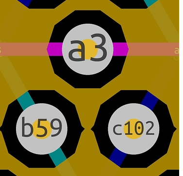
Now compare that with the gerber for the orange GND plane in Gramotey’s screenshot:

For each hole in the GND plane, the GND plane is directed around each via with a low poly approximation of a circle. In this case each hole is constructed out of 10 straight line segments, and thus 10 lines of Gerber code.
If it were possible to use the negative gerbers in the GND plane just as in the solder mask, then each group of 10 line segments could be replaced by one aperture flash. This will result in a reduction of filesize of 90% for all the via holes. And for 115000 holes that would save more then a million lines in the gerber file.
If file size is that important then you could hack into the files, either with a text editor or by writing a script, and then remove a lot of the internal structure of the GND plane, and replace it with the negatively defined features such as in the solder mask layer.
Normally via’s are covered by solder mask and therefore not in the solder mask layer, but probably are if you turn of the “tented via” option during gerber creation.


 for proton cancer radiotherapy.


