This isn’t directly related to KiCad, although it does involve a footprint from the standard library.
I’m using the footprint Connectors_JST:JST_SH_SM04B-SRSS-TB_04x1.00mm_Angled for this connector.
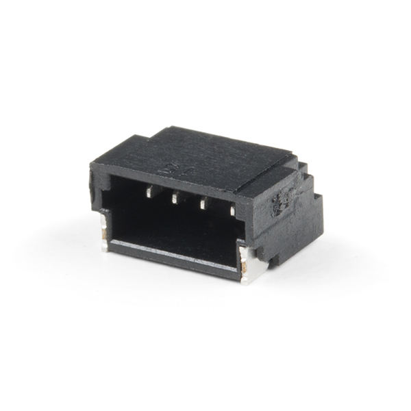
I’m hand-soldering this connector, and I’m finding it difficult. It wasn’t too hard to solder the four signal pins, but the problem is the mounting pins. The two mounting pins have very little exposed area on the sides of the connector, so it’s difficult to get in there with a soldering iron and solder them. (Especially without melting the connector.)
This picture shows the mounting pin and how it is sort of recessed inside the plastic housing.
Is there some trick for getting the solder in there? Or should I be looking at alternative means to hold the connector in place, such as epoxy or cyanoacrylate?
If your only tool is a single soldering iron, I’d ensure that it has a fine-ish point. I’d probably put a very small amount of solder on the mounting points but not enough to reduce alignment of the connector.
Then I’d make sure that the connector is held in place first by a single pin on the rear being soldered first. This will allow you to wiggle it into precise alignment by only needing to solder a single point.
Next I would solder the remaining rear pins. This would ensure that it is electrically connected properly regardless of how the mounting soldering goes.
Then I would make sure there is plenty of flux over the front mounting points, and then hit with some heat on the side of the mounting point. Apply solder. Then apply a bit more flux, then hit the pad with the soldering iron. Hopefully there is enough heat, solder and flux to ensure wetting and flow between those two points.
Otherwise, some solderpaste and a reflow oven would do the trick. Plenty of vexamples of using solderpaste and a small sandwich oven exist on the web…
The standard libraries include footprints for some components, specifically designated as “Hand_Solder”. When enlarging the pads, take a look at the component and enlarge the pads in a direction that best improves access for your soldering iron. I.e., a larger pad doesn’t help you if the enlargement is hidden under the connector’s body.
I use an electric skillet, without fancy control circuit, stock as it came from the second-hand store. Once you use solder (either leaded or unleaded) or flux inside a kitchen appliance, make sure it is never again used for food preparation.
When manually soldering, you can use a hot plate or the electric skillet to pre-heat the board before soldering the connector in place. With the board and connectors already heated well above room temperature it’s easier for the soldering iron to heat the joint to the solder’s melting temperature. Watch out for fried fingers!
Even without the toaster oven or skillet you can try soldering your connector using your soldering iron and paste solder (e.g., Kester EP256 from CML Supply) rather than wire solder. The solder paste is a mixture of finely ground solder and flux. Use a toothpick, sewing needle, or dental probe to apply a thin layer to each of your connector’s mounting pads. A small amount goes a long way. The solder will melt and flow when touched by just the fine tip of your soldering iron, without the need to get any flux or additional solder onto the pad.
Yes, I should probably enlarge the pads. I’ll do that next time I fab the board.
I’ve been meaning to learn reflow, although I had been hoping to do this project without it. (My current project is entirely through-hole, except for this one connector that wasn’t available in a through-hole version.)
I like the idea of using solder paste with the soldering iron. I’ll probably give that a try.
I tried it with the solder paste and soldering iron, and that didn’t work. (The connector came off easily after I’d soldered it.) I guess the problem is that the mounting pins themselves aren’t getting heated, so it forms a cold solder joint.
So, I think I will have to finally learn to do reflow. I actually bought a REFLO oven a while ago. There is some assembly required, and then I have to learn how to use it, so I’ve been putting it off. Maybe it isn’t as complicated as I think, though. I guess this project is the perfect excuse to finally do it.
(I believe the capacity of the REFLO is 3 inches by 2 inches, and my board is 3.05 inches by 1.8 inches, so I may need to file down the board to get the width down to 3 inches.)
The bigger problem is that I’m going to release this board as open source. It seems that this JST SH connector is not reasonably hand-solderable by someone with average skill and equipment. So in the next iteration of the board, I may need to replace the JST SH connector with a through-hole JST PH connector, and hope that SparkFun keeps selling these adapter cables.
Can you put both foot prints on the board and keep the pads from overlapping? Through hole parts would let someone solder wires and let them come up with their own solution for connecting if needed.
It turned out to be about as bad as I thought, but I’ve finished the assembly. The assembly was fiddly, and there was one major thing and several minor things missing from the instructions. And then it looks like I may need to recompile the firmware and upload it to the oven. Still, I’m getting closer.
I had already released version 1.0 (which did not have the connector), but I’ve gone ahead and pushed version 2.0 to GitHub now. The photographs are still of version 1.0, so they won’t match the KiCad files.
You don’t have solid connections but it’s still possible that the copper nearby conducts heat away. If the design was mine and I was desperate I would try something like this (just a rough demo):
I don’t know how experienced you are with hand soldering, but I know from experience to not try to save flux. Maybe the paste itself isn’t enough. And Sn without Pb is more difficult. Again: with good amount of flux impossible becomes easy.
I have met quite many cheap usb plugs whose pads have taken as their mission to spurn every tin molecule. This metal may be like that. You could try to presolder just the metal parts of the connector (with enough flux!). If it succeeds a cold joint is improbable when soldering the part to the board.
I just looked at the campaign (for the first time), and the specs say 2" x 2". You’d have to remove over 1 inch (roughly one third of your design) to fit.
This might work. Just don’t linger too long putting a blob of solder on the connector tabs. But it might be easier to flow the blob onto the board pad with enough flux than to try to flow onto both the board at tab at the same time.
A portable reflow oven? How bizarre! A T962 seems far more useful.
Anyway, for this type of connection the standard hand-solder approach is to create a longer pad, put a dab of flux on the pad, then heat the pad with tip and apply solder so that it hopefully flows under the tab and forms a good connection. It is still a bit tricky and you need to leave space around the connector to get the right angle with the iron.
If you do a lot of these type of connectors then might be worth getting into reflow, of course when you do have reflow skills it opens up a lot more possibilities. I’m currently considering getting a T962, but I need to clear some space first!
Not particularly, especially not with SMT parts. The only surface-mount parts I’ve soldered before are a few 0805 resistors and capacitors.
Yes, they seem not to have updated that on the campaign page. I received an update via email that said they changed it to 3" x 2". (That update seems to have been email-only, because I don’t see it in the updates tab of the campaign.) If I measure the cavity, it is 3" x 3", but perhaps they are recommending a maximum of 3" x 2" because there needs to be room for airflow.
Seems like this should be doable. For big difficult parts I often try to tin them up with a bit of solder on the part by itself. Once on there it’s easier to join on the board solder as it welds together easily. Lots of flux and I’ve had little problem with such parts. Up the heat a bit too. Big slabs of metal soak away the heat and make it more difficult to get a good joint.
I tried doing that, and the mounting pin came off and stuck to the tip of my soldering iron. It’s a tiny, flimsy piece of metal, and I guess I melted the plastic just enough for it to be able to detach.
Meanwhile, I’ve been working on the REFLO oven. I was able to get my phone to connect the oven, but it claims the current temperature of the oven is 2047 degrees C. So, I’m waiting for a response from the creator of the REFLO.
I have no knowledge of this specific design but does your oven design have a thermocouple? If so, this is polarity sensitive and you may have it connected the wrong way around. Try connecting it the other way.
I tried doing that, and the mounting pin came off and stuck to the tip of my soldering iron. It’s a tiny, flimsy piece of metal, and I guess I melted the plastic just enough for it to be able to detach.
It does have a thermocouple, but it was marked with the polarity, and I connected it according to the instructions. I could try reversing it, though. Will that cause any harm if I had it the right way the first time?
The creator got back to me and said it might be the circuit board, and he’s going to send me a new circuit board.
It shouldn’t cause any damage if you have the polarity on a TC reversed - it just will work backwards. Easy test - if you can somehow warm the thermocouple up a bit - does the indicated temperature go up or down? If it goes down, the TC is probably the wrong way around. If it goes up but the reading is nonsensical the problem might need a bit more investigation.


