Hello Everyone! Currently i am struggling finish my bachelor degree, due to one error i keep having it, and this one is:
Circuit: KiCad schematic
Error on line 5 or its substitute:
osc1 net-r10-pad1 net-r8-pad2 55 hz
Unable to find definition of model
Background thread stopped with timeout = 0
Error: circuit not parsed.
Well, what is “osc1”? If it it’s a signal, it’d normally be a “VSIN” spice source. And why do you have ground symbols in the middle of connections?
That little error is the least of your troubles, there’s much more, but the simulation stopped before all the other problems were reported.
ote: No compatibility mode selected!
warning, can’t find model ‘net-r2-pad2’ from line
u1 net-r7-pad2 net-r5-pad2 net-r1-pad1 net-r2-pad2 net-r6-pad1 net-r6-pad2 net-r11-pad2 net-r11-pad1 net-r10-pad1 lm324a
Circuit: KiCad schematic
Error on line 2 or its substitute:
u1 net-r7-pad2 net-r5-pad2 net-r1-pad1 net-r2-pad2 net-r6-pad1 net-r6-pad2 net-r11-pad2 net-r11-pad1 net-r10-pad1 lm324a
Unable to find definition of model net-r2-pad2
Error: circuit not parsed.
Well, you still need a ground connection, otherwise nothing will simulate.
Are your capacitors really 3 and 15 Farad?
Did you run a DRC before trying to simulate?
You need more parameters for the VSIN sources. Where did you get those from? The working ones are in the “Simulation Spice” library.
No compatibility mode selected!
Circuit: KiCad schematic
Too many parameters for subcircuit type “lm324” (instance: xxu1)
Error: there aren’t any circuits loaded.
I don’t wonder that it doesn’t work.
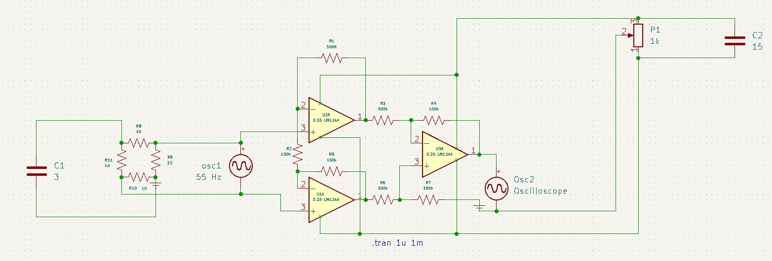
U1 and U2 are DC voltage sources that are drawn upside down. Not 3 and 15 F capacitors.
Osc1 and Osc2 are fantasies that don’t exist in spice.
There is no ground connection anywhere.
Apart from that, the function of P1 eludes me.
It’s apparently an instrumentation amplifier drawn by someone with limited knowledge.
This all system is a combination of Those 2 draws that i marked with yellow and red, and those blues lines( With Osc1, Osc2, U1, U2 and P1) …all this drawn by my proffesor
In the meantime, i am thinking of changing those Amplifiers with Transistors and deleting those Oscillators and have one more look over those Cappactors and Potentiometer
I expect Osc1 and Osc2 are intended to be Oscilloscopes (display of voltage), not Oscillators.
U1 and U2 are variable voltage supplies (drawn as batteries), not Capacitors. Note that convention is to have the long bar of a battery represent the positive pole, and I suspect they’re drawn upside-down.
P1 makes no sense as drawn, unless you ignore the ground symbol. If you assume the negative pole of U2 (power to the IC) is ground, P1 changes the bias of the input to the second stage +input.
I also have 3 Op-Amp, and i do not know how to work with them. Only with 2.
No compatibility mode selected!
Warning: redefinition of .subckt tl072c, ignored
Circuit: KiCad schematic
Too few parameters for subcircuit type “tl072c” (instance: xxu1)
Too few parameters for subcircuit type “tl072c” (instance: xxu2)
Too few parameters for subcircuit type “tl072c” (instance: xxu3)
Error: there aren’t any circuits loaded.
I think this is because i worked with those 3 Op-AMP in the same way i would work with 2
Forget all that and get the circuit fixed first. You are trying to simulate a broken schematic and it’ll never work.
No more from me, you don’t listen.


