Symbol Fields Table in Hierarchical Schematics ... can't limit scope to current sheet

I use the Symbol Fields Table heavily when I’m trying to clean up and populate fields (like Manufacturer, and Mfg Number) with missing information after basic schematic entry. I’m running into trouble doing this with a larger hierarchical design with design sections pulled in from multiple unrelated design locations.

I’m moving a design from one external location to another in a hierarchical (larger system) schematic with B-Size pages, (read—“lots of components”). The problem I’m running into is the Symbol Fields Table includes all components in the hierarchy, with no ability to limit Symbol Fields Table scope to the current working sheet. This means there are multiple C13’s, R12’s, etc. showing up from other hierarchical pages when all I want is the current page with original designators needed for design transfer debug. Once fully debugged/transferred, I can reannotate the hierarchy to remove duplicate designators. Until I get to this point in the design merge/entry process, having all hierarchy components mixed in (as it currently functions) makes a difficult mess to untangle.

I’m not sure if what I’m asking is a new feature request, or if there is a better way to accomplish what I’m doing with KiCad by following a different procedure. My current thinking is I’ll have to enter the design into KiCad in a separate flat file sheet, and after debug of this transfer, copy the page from the separate design into the Hierarchy for system level reannotation.

I notice this Symbol Fields Table behavior is the same in KiCad 6.0.11 and KiCad 7.0-rc2.

This is a big red flag:

With Schematic Editor / Tools / Annotate Schematic you have the option to add an offset of either 100 or 1000 for each page:

This would also make it a lot easier to know which part is on which page of the schematic in the Edit Symbol Fields dialog.

As far as I know, there is no possibility to limit the Edit Symbol Fields to a single sheet. Fixing the annotation should already make it a lot easier for you. I do think there is merit in an option to keep this dialog to a single sheet, but I do not work with very big and complex schematics myself. Maybe it’s worth a feature request, but I’m not sure.

WRONG! Please ignore this post! Sorry.
The Annotate function also came to my mind, but it might be refined a bit more than just the x100 or x1000 option.
Every sheet in a hierachical schematic has its own .kicad_sch file.
Open each of these from your file manager (not KiCAD) and do the annotation (eg, sheet1 with “Use first free number after 100”), and save it afterwards. Do the same with sheet2 using 200 instead etc.
This should give you unique symbol references, numbered per sheet. You need to make sure that each sheet doesn’t have more than 100 references per symbol type. :slight_smile:
DISCLAIMER: I’ve never tried this myself, so as always take a backup first.

Let us know how it came out.

Cheers.

EDIT: just tried it myself and it works. But it’s very important that only the .kicad_sch file is open. If the .kicad_pro file is open at the same time, everything will be newly annotated.

This is called Standalone Mode in KiCad, and this changes some menu’s both for the schematic editor and the PCB editor. I’m not entirely sure it should be used here though. The Annotate Schematic has an option to limit the scope to the Current Sheet Only.

I’ve tested it now. Forget my previous “recipe”, please.
This works: Open the .kicad_pro file with the top/main sheet.
Enter each subsheet and do the annotation with 100, 200, 300 etc. as previously described, but be sure to select the “Current sheet only” option.
Save and exit.
Now the annotations are all new.

The issue is, that in a multi-sheet schematic, the annotations are stored in the project file, and will revert to previous state if you only modify the .kicad_sch sub-sheet.

I’m unable to open the Kicad_sch from File Manager. But your idea is sound, if I can create a SheetName.kicad_pro file to maintain a separate set of Annotations which match the original design for translation review. This may accomplish what I need for this one sheet.

There are other sheets in this design which follow a “complex” 1:many hierarchy. Not having another copy of the schematic sheet around satisfies my sense of good engineering practice for larger systems, only document in one place, reference in others. Complex means the same schematic design/sheet is used multiple times with different components in separate places in a larger design. As such, each instance of the schematic page is a different collection of parts. The sheet can’t be opened without the context of a .kicad_pro file. I know this from another design I made using KiCad to produce a complex hierarchy (which worked well for what I needed to do).

As an example, let’s say you have a 3.3VDC switching supply used in 9 different places in the final assembly. The design is the same, but the final assembly (which might all be on the same PCB) are not. In a complex hierarchy, the relationship of schematic page to BOM is not 1:1, rather 1:many.

I don’t need to keep the original annotations around after reannotation. However, previous experience suggests the original “standalone” designators will stay in the standalone sheet.kicad_pro file , and have different annotations stored in .kicad_pro when used in the hierarchy. This can be useful if there are questions about the initial translation, which can be referenced by opening the schematic in “standalone mode” using the Sheet.Kicad_pro file.

Anyway, thank you, @paulvdh and @ML9104. I now have two possible solutions better than what I was planning to work around this issue.

I am a bit confused by the … does not appear to be an Eeschema file message. Normally you should be able to open a hierarchical sheet in the Standalone Mode as ML9104 suggests. But there is a limitation. Because an hierarchical sheet can be used multiple times in a project, (And I think it can even be shared between different projects) there have to be some “tricks” with the annotation. I think the annotation is saved in the sheet where it is included from. Maybe in the “hierarchical symbol”, but I’m guessing here, I am not sure at all about the details.

No, I checked the different files. In a hierachical schematic (and perhaps also simple sheets, I didn’t check), the annotations are stored in the project file.

1 Like

@craigarno : I’m not sure if what I’m asking is a new feature request …

Yes, it’s a currently missing feature. I filed a gitlab-issue a long time ago, but it got not that much attention (despite I think it’s good relation between necessary programming effort and resulting enhancement of user-experience).
You could look at Wish: enable more eeschema --> Tools to work with a selection (#9008) · Issues · KiCad / KiCad Source Code / kicad · GitLab. Maybe I made a mistake at bundling 3 tools into one gitlab-issue.

What I did to accomplish the task I needed is slightly involved, as-in find a way to thread the needle type involved, so I’ll document the process here.

First, I require the sheet to be “Standalone” so I could enter component designators from the original design, which might conflict with other sheets still in various stages of work in the KiCad hierarchy. Then I need to transfer original design BOM information using the Symbol Fields Table tool. This must be done, so I can export a KiCad BOM for comparison with the original design, looking for discrepancies. This must be done so nothing is missing from translating the original design, so it can be picked up and modified for the current application. As a final step, I like to run KiCost on the result to make final tweaks so everything works. This corner of the design doesn’t require SPICE, so that step is left out. During the time we’ve spent discussing this topic, I’ve completed the current B-Size sheet following this process.

To get the Standalone sheet I somewhat followed @ML9104’s original suggestion. To do this I had to follow these steps, exactly:

  1. Open the original KiCad project file for the hierarchy in KiCad, and no other files. This loads the component information needed to prevent the “eeschema Warning Dialog” I showed earlier.

  2. Open MS File manager to the project location. Double-click on the file which needs to be worked on standalone. It will open this time because component information is already loaded from the prior step.

  3. Now create the “KiCad Standalone Project” .kicad_pro by selecting File->Save As… in eeschema
    image
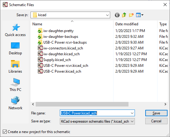
    … and notice “Create a new project for this schematic” is selected in the bottom left of this dialog. This will create the Sheet.kicad_pro file needed for the operations described in the second paragraph of this message.

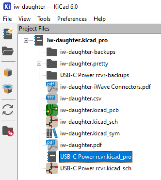
  4. From here, double-click on the newly made Sheet.kicad_pro which now shows up in the Main KiCad project dialog
    image

  5. Notice the file list is resorted and the schematic for this KiCad standalone effort is at the top of the list
    image
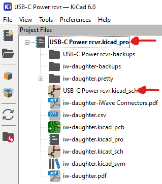
    This single page can now be operated on as described in the second paragraph of this message.

The problem with this approach is the page is literally standalone. The component designators stored in the Hierarchy.kicad_pro file don’t get updated with edits in this document. This is a relatively minor inconvenience for all the operations I need to perform while developing this standalone schematic. Once the standalone is complete, I suspect I can copy the entire schematic with modified component designators, open the Hierarchy version, and paste the new data into the Hierarchy. The schematic will already be up-to-date, because after all, we’re working with the same file/page in the design. So all we’re really doing is copying component data fields from the Sheet.kicad_pro to the Hierarchy.kicad_pro.

From here, I can use Annotate tools in the Hierarchy work area to perform the operations described by @paulvdh to clean up the last 10% of the job, which I usually report as “System Integration”. In my experience on many of these types of jobs over decades, 10%-15% is about accurate when reporting schedule milestones. Schedule milestones are needed by Program Managers, Managers who are trying to figure out schedule, cost, manpower, and next project planning while I do the engineering work. Other downline groups like Manufacturing, Test, Marketing like to know when they can expect a finished design too. So this drives a lot of work outside my direct responsibility.

For hierarchy annotation, a more flexible approach might be to use a number mask to define which part of the component number is the “page” and which part is the original component. This way, I may be able to keep the original page component designator values while overlaying page number information to the original component values. The concept is similar to using a Netmask in Internet IP numbers… you know the 255.255.255.0 or /24 notation. This describes what part of the number is the Network part, and which is the Subnet ID/Device part. This will make it easier to trace inherited designs and compare to the submodule design used in the system. i.e., R101 might refer to page 1, component 1, or R101 depending on the component number mask. Or R1001 if the mask is set differently to allow more than 99 different R’s and C’s in the same design page. A simple “PPPNN” mask notation with the option to only overwrite/update page information might be useful. Or just a single digit number field 1-9 which describes the location of the Page/Number boundary location. I only use A and B size pages in my designs because we no longer have C and larger page plotters or ammonia based blueprint machines for schematic copies in a document center. Most office (and some home) locations can print Letter(8.5x11), Legal(8.5x14), and Tabloid(17x11) size pages. For anyone asking why you’d need more than 100 R’s on a B-size page, think processor bus termination for 64-bit or 128-bit wide buses needing high speed design treatment for transmission line waveform integrity on a bus.

1 Like

Jeez!! What a lot of work. The main upside is, that all the design files are in text format, allowing you to examine what’s there. There are other programs that won’t allow that.
But it takes grunt. Chapeaux!

Actually, “fixing the annotation” is the “last step” in the process of moving an existing design into the hierarchy. Doing this up front, prematurely, will break any hope of traceability needed for debug of the relocated design.

When entering an existing design block, the component designators must match the existing source design. This matching is required, so all bypass caps and other parts can be accounted for. Renumbering these parts makes it nearly impossible to compare the original design with the newly entered one if the numbering is different. This is why I require a “Current Sheet ONLY” or, as I finally did, make a standalone design, so I can accomplish this outside of (by defeating) the hierarchy before reintegrating the standalone design with the hierarchy. Defeating the hierarchy to get design entry properly performed is not a good work flow. Renumbering prematurely means I have to look at a BOM and decide, is C25 in the original design equal to C1214 in the new design? Then hunt around two slightly different schematic drawings to figure out where the parts finally landed, so the two equal designs can be compared. It becomes a nightmare quickly. Nightmare→Will be full of errors. So, NO, the parts can’t be renumbered until the two designs/BOM’s are reconciled. Once reconciled, then the design tether with the original can be cut with a reannotation for the new system design. Until reannotation happens, the Symbol Fields Table can’t be used in the Hierarchical design, because it can’t be told to ignore other work in progress in other parts of the hierarchy.

Think of this another way, to stay productive in a larger design, it is important to only work on/focus on one room at a time. There is no way to focus on the “whole design” when most of the parts are incomplete. The last step, Integration, which represents the last 10% of the effort, is when reannotation occurs. What I’m asking for is a way to limit tools like Symbol Fields Table to certain rooms/portions of the design. This is important for other tools like SPICE too. You really don’t want SPICE trying to manage a 5000+ node input circuit deck when all you really want is to analyze a 5-pole elliptical filter at the input to one part of the hierarchical design. The SPICE processing overhead would be enormous, and SPICE will either crash or take forever to complete, which again makes debug impossible.

In larger (non-trivial) designs, there must be a way to look at only the subsections of interest, which in a good hierarchical design will mostly be on a subsheet or two of the larger system design. I say “good” design because I’ve seen hierarchical designs used to shred a design so all the pieces will fit on A-Size pages, just to make the documentation work on a cheap office printer. This is like trying to look at all the pieces of a jigsaw puzzle while they’re still in the box to figure out the bigger picture of what you’re building, an impossible task.

It looks like this is going to be a larger discussion than I anticipated.

We may have to drag someone like @JeffYoung or @stambaughw into this for direction discussion.

Can you attach an example project/hierachy, even as simple example as possible to show the problem and what you are trying to do? It’s difficult to imagine what you actually have, and we might come up with something new on top of the other propositions.

I got the flu last week, which pretty much stopped me. I’m still not feeling well, run out of energy quickly.

I considered “simple” examples, even have one partially built, however from comments and questions posted here, I suspect a “Simple”/trivial example will not demonstrate the problem of larger system design. This is because in a “simple” example, there are too many easier/simpler ways to solve the problem. This means that unless you have the right background, some explanation is required to help appreciate the issue.

My intention is to work with the KiCad team to further explain this issue. The comments here are “good”, but they only apply to the last 10%-15% of the work. The reason I want to do this is I think everyone involved, including myself, will get a better tool once the design process for larger systems is better understood. Not to worry, I’ve worked as a consultant in about 7 different large, well known companies, so this knowledge is not specific to how one company conducts itself internally. I don’t think there are any quick fixes to be had without this understanding. This is going to take some time. And from my perspective, which may not match yours, KiCad is almost there, just a few “simple” changes… which is why I thought posting in a forum was going to resolve this. We’ll see how right/wrong I was on this thought.

The basic workflow has to be:

  1. Pull in subcircuits from existing designs (simulations, napkins, previous schematics) into separate hierarchical sheets, which may be nested more than 1 level.

  2. Maintain Component designators from the original design to maintain traceability to the source design schematic and BOM. This makes final import crosscheck and review possible by comparing KiCad generated BOM information with original design BOM information and making corrections with KiCad’s Symbol Fields Table" tool. It is at this step that I’m having trouble with KiCad tools, which can’t limit hierarchy scope and confuse information by dragging in all system level project component designators and mixing them all up. This is a problem because almost all other designs being integrated are going to have a R1, C1, Q1, U1, and you’ll see this from all the other designs being imported. Most of the time, these components on other sheets will have different values, different vendors, different part numbers, etc.

  3. Once each imported design is verified/validated, then and only then can top level annotation be applied to produce unique component designators across the whole assembly.

And the issue which brought this up is not even a large system. I suspect what I’m working on using KiCad will end up being fewer than 1000 nets.

I notice the Annotate Schematic dialog already has the scope limiting code I need in the “Symbol Fields Table”. This is what I’m asking for in the schematic “Symbol Fields Table” tool:
image
Notice there are duplicates, like two C4’s:


Notice the BOM also doesn’t have the ability to limit scope.

Again, what’s needed is similar to the Annotate Schematic dialog. Both tools need scope limiting for early design entry in a hierarchy. There may be more than 1 person performing design entry for larger designs on different hierarchy sheets. This might be for a group of 20 engineers working on an ultrasound machine design, or next gen radar design.

As a workaround you can add a custom field and set it to the sheet number (or name). Then you can at least see on which sheet each part is, and you can probably also use the Group By function.

An intriguing idea I hadn’t considered. I’ll keep this in mind if the “Standalone” procedure I identified above runs into trouble.

I should add this doesn’t address BOM generation. Basically a designer stays in a loop editing components and generating BOM from the sheet/sub-heirarchy for comparison with the original design. This doesn’t end until they match.

Once all the pieces are entered into the system design, then the work of modifying to meet interface and system performance needs begins. This is necessary to meet clock edge timing for multiple destinations, fanout, setup/hold times, transmission line analysis, and other required system tuning can begin. This will lock down frequencies across the system. And of course the usual things to meet EMI for both radiation and susceptibility.

@mf_ibfeew I think my request covers “Edit symbol fields” which now appears to be called “Symbol Fields Table” in 6.0.x and 7.0.0 releases. You might see if you can come up with Use cases where the other two features are important to the end user (you). Or lacking Use cases, find another compelling argument. This might be your opportunity, as I can only guess at why these might be needed. What would you do with these features, and why?
“Clearer View” sounds good. What do you mean? If any of my previous arguments for Symbol Fields Table gives you ideas, feel free. I don’t want to miss any potentially essential KiCad features in this discussion.

"Clearer View” sounds good. What do you mean?

With my biggest design I have >800 symbols. I think it’s the same argument as yours - finding the desired symbol between 800 lines of symbols is difficult. So limit the displayed amount of symbols to the current sheet or the current selection would increase the clarity.

I think my request covers “Edit symbol fields” which now appears to be called “Symbol Fields Table” in 6.0.x and 7.0.0 releases

Yes. The other two tools are similar. I don’t use them myself (not my usecase / my workflow). But the layout is the same - if someone uses them they would benefit from limiting the displayed amount of symbols/lines in the dialog.

Let’s see (and hope) that someone takes on the programming task. (You could upvote the feature request to increase the issue-weight, indicating to the developers that we can’t live without that feature).

What I’m hearing is we have similar KiCAD feature/UI issues encountered when working with medium to large design efforts.

I hope this will get traction, as it will make KiCad more usable and is needed for wider KiCad adoption.

This discussion is now referenced within the GitLab Issue Wish: enable more eeschema --> Tools to work with a selection (#9008) · Issues · KiCad / KiCad Source Code / kicad · GitLab