I don’t often use relays in my projects but I was investigating a simple circuit that required a relay. At this point any DPDT relay would do.
My surprise and questions is:
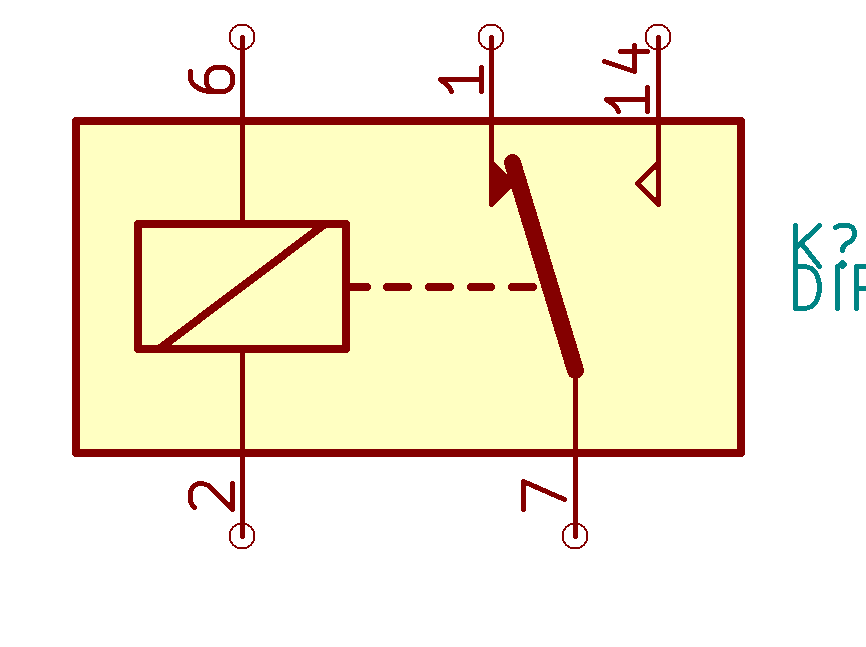
It seems all the relays in the standard library are drawn in what appears to be the “energized coil” position. I had always drawn relays in the unenergized position where the moveable relay element was furthest away from the coil.
I also see the “contact” point on the stationary contacts have a filled or not filled configuration. From a standards view I’m not aware of the meaning of such a graphic.
Is there some recent standard for drawing a relay in such a manner?
When making my own symbols, I solved this problem by adding a line of text next to the switching unit saying ‘note: relay shown in (de)energised position.’ No ambiguity whatsoever.
And yes, I’ve separated the coil and the switch(es) to separate units.
The relays library is a bit of a mixed bag. Originally i planned to work on a general standard to maybe allow the use of a few generic symbols following some official standard to represent most relays. However, i never found the time to really do that.
Based on that symbol I would assume pin 1 is NC (connected to pin 7 when coil is de-energized) and pin 14 is NO (connected to pin 7 when coil is energized). Is that not correct?
You are likely correct. However relays in the past (and in most relay data sheets) show the movable contact furthest from the coil when not energized. This mimics the mechanics of a standard relay.
I don’t have a recent copy of any standards, but here is what my (possibly illegal and/or obsolete) copy of the IEEE Std 315-1975 shows for relays.
Note how in all cases the NC contact is away from the relay, unlike the screenshot in the OP.
I thought there might have been a mention in this standard about filled contacts indicating NC and empty contacts indicating NO, but I couldn’t find that in my quick scanning of my PDF. Either I missed it, I saw that somewhere else, or I made that up.
I see. Never realized that the proximity from the coil encoded information, but I guess that makes sense. The wikipedia article for “relay” has one image that does not follow this convention (at the top) and one image that does (at the bottom).
It seems like there are several different ways to encode NC vs. NO (proximity to coil, filled vs. unfilled contact, and resting position == NC). The proximity to coil and resting position conventions both have the disadvantage that there’s no way to tell if the drawer was aware of the convention or not.
Great reference! It made me see the part that I found unintuitive. In your post and @BlackCoffee’s post the relay coil did not show any coupling to the contacts (similar to what you would find in a ladder diagram). In the symbol I posted the dotted line from coil to contacts I always visualized as the mechanical coupling, hence my expectation of the movable contact position when the relay was de-energized.
I never heard of a convention that the contact closest to the coils would be the un-energized position, but instead that relays are always drawn in un-energized state.
Last time I needed a relay in KiCad, I had to draw my own symbol. I do not like the mating of the coil and contacts in the same symbol, so I made Units A and B for the contacts, and Unit C for the coil.
There are different standards all over the world for that. I learned it from the german standard DIN 40900-x. This standard basically tells us the following two rules:
All contacts (relays, switches, …) are drawn in their non actuated position (buttons are not pressed by the user and relay coils are not energized). Exceptions are allowed if it makes the function clearer or if the component is build such that actuated is the normal condition, however this must then be clearly indicated. (A typical example for the use of this exception is the emergency stop loop.)
In general the actuation is always left to right or top to bottom. This makes it easier to read a schematic. Also be aware that schematics that make heavy use of relays typically split symbols up such that the coil and contacts can be placed separately possibly even on different pages. Especially in such a case your rule would no longer make any sense at all.
There are a couple relays that are split in the library for a starting point to make your own (instead of starting from scratch):
Relay:FRT5_separated and Relay:G5V-2_Split are both 3 unit DPDT relays (unit A = coil, units B&C = SPDT contacts).
I just realized the OP was about contacts “leaning” toward the coil, implying they’re currently being attracted by it. Totally missed that notion before.
To answer that question:
I’m not familiar with that being a consideration in drawings. Getting back to the IEC example above, that drawing combines the basic symbols “operating device, general symbol”, “make contact” and a dashed “linkage” line. No assumption is made about the actual, physical process actuating the switch and “make contact” just happens to be drawn to the left.
The actuator might not be actually pulling on the contact and the full drawing might include several operating devices, drawn in all directions from the contact and employing different mechanisms, so trying to include the direction of any physical forces and movement of parts in symbols doesn’t make much sense.
I have always (being very old and now retired) used the coil “pulling” the bar operating the contacts, with the coil and contacts shown in the “resting” position. I very rarely use relays and I think the last time I did, I drew the coil separately and used two SPDT switches in the schematic which meant I had to draw the footprint freehand. I do think it makes logical sense to show the relay “de-energised” and the contacts in their “resting” state, irrespective of whether that should be the NC or NO contact if it is a SPST relay.
Concerning the reference designation of the individual pieces of a relay (or contactor). ANSI/ASME Y14.44 Clause 2.1.6.2 Elements of Relays has three methods, of which I have always used the third method. This is an extension of the Unit Numbering Method and reference is made to Figure 2.1.7 example that is as follows: The relay (or contactor) part/component would use a reference designation of K#; the operating coil would use a ref des of K#L1; the first set of contacts would use a ref des of K#S1; the 2nd set of contacts would use a ref des of K#S2; etc.
–Larry