Is that I2C or SPI broken out separately ?
Yep…
Each manufacturer’s Arduinos are a bit different. On one hand, it’s what’s good about Open Source… With a working schematic, they can lay out the boards any way they want. On the other hand, it basically requires a different footprint for each manufacturer, and that can also vary with each version they release.
Ah sorry, my brain wasn’t working, I remember what happened now, I found two types of boards, so I did a footprint to cater for both types. The “second set” is actually A4,A5,A6,A7 in an alternative place.
Type 1

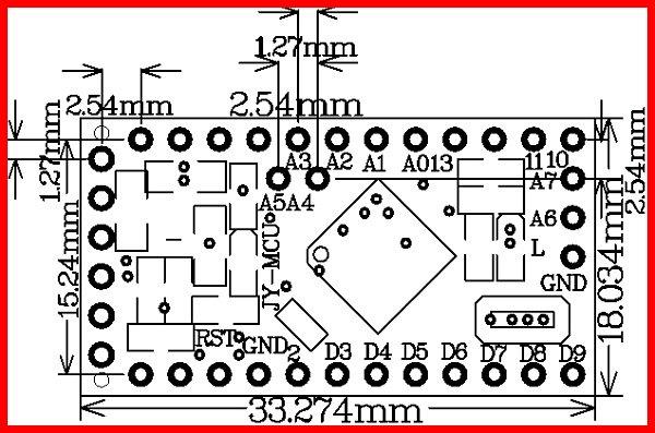
Type 2

There are almost too many variations to catalog!
Exactly. That top one is a Sparkfun board. Bottom one China ?
Most of the Chinese seem to copy one of the Sparkfun variants.
I think the second is marked “Baite”, not sure whether they are designer or just add the brand. Of course, there are now copies of that board…
Yep.
Anyway, we’ve drifted off-topic here. Trying to get back to the original topic…
It just strikes me as odd that the footprint editor doesn’t seem to allow direct manipulation of an item created with bitmap2component… Can’t directly select it, rotate it, move it, delete it… Or at least I didn’t find a way.
I did have a thought on that. Pressing the T key (get and move footprint) then typing the reference name (“G***”) makes the footprint stick to the cursor. So you can move it, but there doesn’t appear to be a context menu item to delete it.
In general, right clicking near the anchor point of the footprint allows it to be selected, although sometimes it is a bit dodgy. It might help to have the a different layer selected in the layer manager, or a different mode (e.g. “Footprint” mode).
I’m trying that suggestion with this:

I’m getting no response from pressing the T key around anything.
Version 4.06-e0-6349~53~ubuntu14.04.1, release build.
The T key is not context sensitive, it opens a dialog and you have to type the full reference name (there is no wildcard allowed).

Ohh, sorry I am all kinds of wrong today! Somehow my brain was thinking pcbnew. Reset…
The bitmap converter creates a footprint using a poly_line, which in legacy mode is not something that can be created by the user, and the GUI does not allow the user to modify it - nor even select it.
In the “new canvas” (OpenGL, F11) the poly line can be selected using block select (lasso around whole graphic), then it can be moved or deleted.
1 Like
GOT YA !!!
That worked !
I was using the legacy canvas !
Thanks !!

For the Arduino Pro Mini that is discussed at https://www.arduino-board.com/boards/arduino-pro-mini. The post is a little old so there may be even more versions floating around. It’s difficult to find diagrams that actually define the pin locations for any of the variants - the best I found is at http://img.alibaba.com/img/pb/053/955/500/500955053_563.jpg but that’s only one guy’s implementation.
I had the same problem of non-standardization with the ZS-042 Real Time Clock Module that is used on several popular Arduino projects.
Dale
1 Like
Yep…
Just impossible to keep up with all variations.
One would have to document their project as using one particular board and only that board.
That’s what a real MRP system does with approved vendors, alternative parts, etc.
I have done that, but I don’t think the purchasing folks here truly comprehend it.
Dale