Hello! I have installed extra/kicad-library on manjaro linux, I think that it installs the default KiCad library. I’m trying to use the ESP32-S2-WROVER symbol, but I’m having trouble with the pins. The official datasheet is here https://www.espressif.com/sites/default/files/documentation/esp32-s2-wroom_esp32-s2-wroom-i_datasheet_en.pdf and in section “3.1 Pin Layout” there is no GPIO22 anywhere. If I add the symbol to a schematic, then I also do not see GPIO22, but I can see IO45 and IO46.
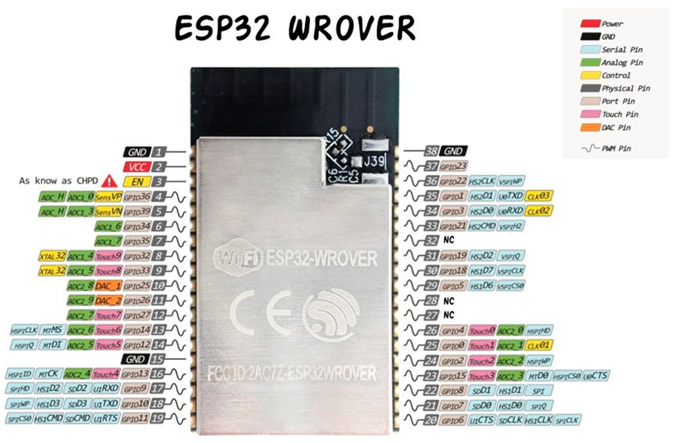
However, on my module, there is no IO45 and IO46, but there is GPIO22 and GPIO23.
I’m really confused. Can I use the ESP32-S2-WROVER symbol for my ESP-WROVER-V4 module? If I can’t, then is there a symbol that I could use? Possibly I can design my own layout if nothing else works, but I’m very new to KiCad (I started using it just a few hours ago), and I think I don’t have enough experience to design my own symbol and layout.
There are lots of (partial) libraries floating around, and from many different sources. The official libraries are vetted quite meticulously, but everything else you find on the 'web will vary in quality. There still can be errors in KiCad’s default libs, you should always verify. However it’s also likely you module is from a different manufacturer. There are many such modules with small differences in between them.
Ability to design my own symbols and footprints is a mayor consideration for adopting an EDA suite, and I checked this out on the first day I started evaluating KiCad. I even did it before attempting to modify any schematic.
Try this:
Put the symbol in your schematic.
Edit it properties (hover over it and press e).
Click on the Edit Symbol button. This loads it in the symbol editor.
Change some pin numbers, or pin text. (Just for starters).
Simply close the symbol editor, accept it when KiCad asks you whether to save the changes back to your schematic.
That’s all, simple pinout mistakes (or form an incompatible module) can be made in 20 seconds. Verifying whether a whole pinout is correct is more work, and to make it complete you also have to add some library management, but with the simple steps above you already got a good start for making simple modifications on schematic symbols. The procedure for footprints is pretty similar.
I advise strongly that the first few projects you do in KiCad are only for evaluating KiCad itself, and for getting to know the GUI. That way you can concentrate on KiCad itself, and it does not matter whether the actual pinout of your symbols and footprints is correct. After you are familiar with the procedures, it becomes time to apply them to a real project. This decouples the learning of KiCad itself, from the stress of needing to make a proper project. If you’re just experimenting, it does not matter much if your whole PC burns down and you loose the dummy projects. Just create a new dummy project after you’ve bought a new PC. Without beginners stress of damaging a project accidentally, you also have much more incentive to try out things stress free, and this is a great way of learning things. It’s natural to how children learn. Just experiment with random stuff, and stick to what works. Reading manuals and tutorials make this process more efficient, but keeping in the methodology of free experimenting without stress is good for getting started.
That makes it two different modules. Probably similar, but enough to trigger a cautious warning.
Before sending out gerbers, (your some time away from doing that) you should always have a procedure i place for vetting the whole project. Checking all pinouts of all library parts etc. It is very common for companies to only use parts from internal databases, and have people who do nothing else then maintaining such a database (adding new parts, verifying whether the parts are correct, adding metadata, datasheets, ordering info, etc). This allows such companies to delegate such tasks to people with moderate electronics knowledge, while higher tier engineers can focus more on circuit design and less mundane tasks. And those engineers only use the vetted parts from the internal database.
That’s a significant difference. Even a slight change in the name such as ESP32-S3 to ESP32-C3 means a different and incompatible board; one is Extensa based and the other is RISC-V based. You were too hopeful.
