Ah! That is the Cirilo @cbernardo parametric generator, now placed at:
The ancestor and the compiled models are from a relatively early version of the code on the old Sourceforge repository
No doubt the materials on those will look just awful with the new 3Dviewer. I hadn’t touched that code for so long, I doubt that I made improvements to the material appearances. The models are eyecandy only so I don’t care much about their monstrous size. Those VRML tools may be worth maintaining if only for the eyecandy. One good thing about those tools is that you can simply change the material appearance definitions to something sensible and then regenerate all 6000+ models in less than 20s.
I just couldn’t miss your idea and this opportunity and I just created a script using my only know script language C/C++ to generate this!
I created an open source project (GPL3) and generated 1000 1/4w axial resistors wrl files! … more to come latter… project is here:
The model files are distributed under a modified MIT license, but if you need any special license just for you I can think about it!
The Film Resistors zip file is here:
https://github.com/KammutierSpule/kicad3Dmodels/blob/master/generated/Resistors/kicad3Dmodels-Film_Carbon-v0.1.0.zip?raw=true
The zip file is 898Kb and contains already a .png screenshot of 347Kb.
Each wrl file resistor is just 550 bytes length!
The wrl files are based on a recursive include directive of VRML format that will include the seed models and adapt as need.
I created the original models (my first creation) using FreeCAD (file included) the only thing was that the STEP file generated by FreeCAD was not OK 
Then the WRL files were generated with StepUp by @maui
I appreciate if someone with knowledge in this area with FreeCAD can have a look and see if you can generate a proper STEP file because mine was broken. (May I will need to make some adjusts in the design? look for suggestions… )
Also, I appreciate if anyone could review my design (sizes) and resistor values if they are OK.
There are some things to know about this WRL files:
-
It only work on the (upcoming) KiCad 5 (with the new 3DViewer developed by me @kammutierspule with the cache and WRL parser developed by @cbernardo)
-
Every time you use a model, it will be cached by the cache mechanism of the 3DViewer. The cache size per model is 888Kbytes (Maybe @cbernardo one of this days will implement a faster compress system for the cached files

 ) . I think that will be OK if you just use a subset of values on a real case life scenario…
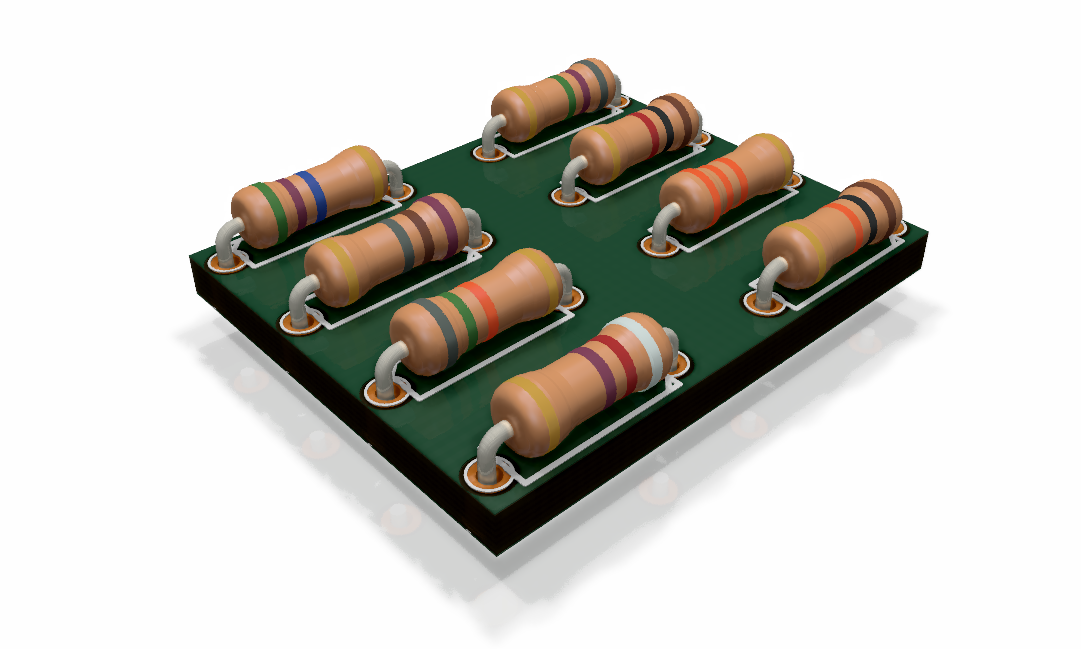
Here is your raytraced screenshot:
Looking for your ideas and comments,.
Other models / variants you would like to see?
7 Likes
Just plain sick. 
Two years from now you guys will be working on getting the solder meniscus implemented. 
1 Like
I had that idea long time ago! … but its not the time yet… may in two years yeah… “we will never know”!
1 Like
I thought about it years ago then decided the model will be way too large and we’d need a compute cluster to push data to shared memory to be rendered. The task isn’t difficult for round thru-holes with round pins/wires, but when you consider slotted PTH or flattened leads for THT, then the numerous fillets for SMD pins we quickly enter the territory of eyecandy absurdity. Even round holes with round pins may not have a fillet visible outside the hole. For the sake of making the job easy, you can simply generate an appropriately shaped blob for each pad (as if it were pad with no hole + solder only) and ignore the fact that it doesn’t quite look right where the solder joins the pin.
I’d guess a pyramid/cone coming up from the pad (custom shaped pads? - get out!  ) would do for eye-candiness.
Height of that contraption could be derived from paste mask layer setback vs pad size and some arbitrary value in a settings file.
Hi Mario,
very nice rendering and models! 
I fixed at least the main body of your resistor (I used a closed sketch to revolve… an open sketch is creating a shell not a filled solid)
resistor.FCStd (17.4 KB)
resistor.step (33.7 KB)
Edit:
release 2 full fixed (with the sketch for sweeping fully constrained)
resistor-ok.FCStd (24.8 KB)
resistor2.step (37.1 KB)

2 Likes
Sorry I am not used to CAD terminology. Closed Sketch? Sweeping fully constrained?
The issue I had with generated STEP was that the metal wires appear cut/splited. and yeah I think I had an issue with the body too.
I will have a look on the file latter, thanks!
This means that there is a full outline. (Think about the edge cuts layer. There it is also necessary that there are graphical elements all the way around. With all endpoints of this elements touching the next one.)
Fully constraint means there is no degree of freedom for any element of the sketch. (In freecad the lines turn green. Also in the left sidebar you can see that there are 0 degrees of freedom.)
With sweeping i guess he meant that your sketch had one degree of freedom left. (I would guess you could move the whole sketch in one direction. But i have not looked at your files.)
1 Like

Closed Sketch = closed path when creating a sketch for revolving

always it is good to have fully constrained sketches, which means no grade of freedom for your sketch

FreeCAD forum is very useful to shorten the learning process
https://forum.freecadweb.org/viewtopic.php?t=11382[quote=“Rene_Poschl, post:74, topic:5049”]
With sweeping i guess he meant that your sketch had one degree of freedom left. (I would guess you could move the whole sketch in one direction
[/quote]
there were non coincident points… very close but non coincident
2 Likes
Wouldn’t a simple solid cylinder resistor look almost as good and be a much smaller model.
Not all resistors have the fat end caps
@davidsrsb You’re talking with people here that create matching colored rings on a 3D model for eye-candy and even contemplate(d) solder meniscus visualization… so, no. 
1 Like
But the leads are not bent over (clinched) on the underside of the board!
Plus you need the leads to be cut at an angle like they would be if you clipped them with side-cutters. Otherwise what’s the point of any of this?
@davidsrsb @SchrodingersGat
baah!  details!
I usually take a top/down approach when going for “detailedness” so thats a bit far away by now
Is there a library policy whether step files would be accepted in the main library? (ofcourse without voiding any license)
regarding the file sizes I can see the R_0201.wings and R_0201.wrl from the official lib adds up to 238,9 kb.
exported from @maui’s script (with material properties) the R_0201.FCStd, R_0201.step and R_0201.wrl file adds up to 65,8 kb.
I would suppose the size is mainly an issue when grabbing way to detailed files from manufacturers.
Step files would be gladly accepted into the official libs, depending on:
- Source of the file ( as discussed above )
- Quality / accuracy of the file
- File size
- How many cookies you are willing to bribe the librarians with.
@Shack is updating the 3D STEP & VRML CadQuery library @github (the one you are a contributor too), aligning the name to kicad libs…
the models are coming from scripted routines based on parameters as in the referred data sheet of the manufacturer, so accuracy should be very good
quality is improved because Materials are implemented as per @kammutierspule materials doc
VRML file size is already much less than Wings3D one
STEP file size has been optimized, compared to the previous models
Ooops, I thought that we were going to be paid with a lot of cookies for offering this gift
FCStd file is not necessary, because the source are a script and a parametric file
1 Like