Maybe it’s time to revitalize Visual effects for item states (#5240) · Issues · KiCad / KiCad Source Code / kicad · GitLab? You can add your use case there as a comment.
1 Like
I don’t think this user is complaining about the markers . . . but the way in which a specific marker is “highlighted” when the issue in the DRC list is clicked.
I don’t know if things have changed in recent versions but I now notice that when I click an issue my mouse cursor is positioned on the position on the PCB where the issue is . . . if I keep my mouse still I can then find the mouse cursor on screen and find the issue. I do use full window crosshairs (for my cursor) though . . . this probably makes this easier.
Not implying that it’s the complete solution but putting this titbit out there as people may think themes are only for layers.
Have you searched in the issue database to see if this has been reported, and if it has been, have you voted for it (with thumb up), and if it hasn’t been, have you filed a new issue? It really seems like a trivial and obvious, but sometimes it just happens that something doesn’t bother other users enough or they just haven’t met that situation, and a developer may wake up when it’s reported for the first time.
That’s why I think “visual states”, or even animation effects, would be great. It could be possible to make many things stand out better which now get easily lost in many situations even when they are highlighted.
I wasn’t aware that I could change the colours of DRC errors/warnings too (I do use a custom theme, but probably never scrolled the extensive colour list all the way to the bottom)…
Changing those does help a bit, but IMHO locating an error/warning is still difficult in some circumstances.
To investigate further, I’ve just set up a layout with several deliberate errors & warnings, close to eachother. In doing so, I discovered something I didn’t notice before. When one clicks on an error line in the DRC dialogue, a small and thin crosshair will appear. So far so good… but not really, because:
- The error crosshair disappears when your mouse cursor leaves the dialogue ! (or enters the layout)
- In this particular case, I ratsnested a small section of a track. The [resulting] DRC crosshair then covered that ratsnest, rendering the underlying ratsnest invisible (since both are 1px thick).
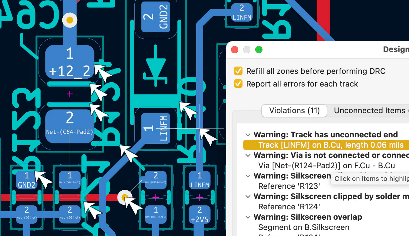
Here’s a screenshot of the setup after I clicked on the DRC warning (rightmost arrow, closest to the DRC dialogue). The missing track sits underneath the crosshair, going to that Pad 1 (LINFM).
https://guyd2.com/KC-DRC_error.jpg
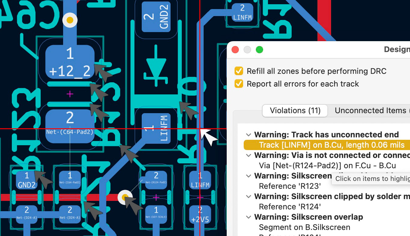
And here’s a suggestion to what I think is a better solution for locating those pesky errors/warnings
(note - I dimmed all arrows but the active one) :
https://guyd2.com/KC-DRC_error-sugg.jpg
So, I think the disappearing crosshair is a bug of some sorts, and I suspect that DRC error tracking could be improved without much re-coding (though I ain’t no programmer).
Cheers,
_g
1 Like
I’m a bit fuzzy on the details, but I recall OrCad Layout had a “High Contrast” mode that toggled everything to grey except the selected object (or toggled everything back to normal). It was useful for finding a selected object on a complex board.
I always zoom right into the board before doing a DRC then when you click on the error/ warning it jumps straight to the middle of the screen and is easy to find.
2 Likes

yes, this is my solution as well - otherwise I have the same problems as @GD2
Being able to import “DesignSpark PCB” files .
DesignSpark is a (almost) free PCB design tool suite managed by RS Components.
I bet there are a lot of hobbyists out there who, like me, switched from DesignSpark to KiCad, and who would be delighted to be able to import their “old” projects for revision in KiCad.
If you are one of them, hit the “Like” button
Thanks.
1 Like
Looks like there’s a way through Pulsonix → PADS → EasyEDA Pro → KiCad
2 Likes
What’s the format like?
If it’s plain text, it shouldn’t be crazy hard.
I figured out ASC (aka boardview) files.
i would like to see this implemented: see video
have a look at this YouTube video from 40:07 thru 41:32 where he demonstrates aligning a 3D part with top of board and holes.
YouTube Channel: “Robert Feranec”
Title: “Tutorial OrCAD and Cadence Allegro PCB Editor | 2022 | Step by step | for beginners”

1 Like
I once used with a Cad package which worked with only one kind of high light. It means that KiCad could and should do the same.
- An improved ngspice embedded plotter (eg.: parametric XY plot with non-time X-axis, personalized background, subplots for more than 2 Y-axes, etc.) See https://gitlab.com/kicad/code/kicad/-/issues/17646
1 Like
I do the same here. ![]()
That looks pretty much like the assembly workbench in FreeCAD.
For KiCad itself, it’s also preferred that the orientation of 3D models is correct without having to make adjustments in KiCad. I guess that over time interoperability between KiCad and FreeCAD will improve. Partly via the KiCad StepUp workbench, but maybe at some future time a (working) assembly workbench from FreeCAD could be ported to KiCad. It’s one of the many advantages of open source software. It’s all freely available and parts can be mixed and matched to improve other programs.
1 Like
Unfortunately, it is not plain text. There are parts in plain text, like the path/name of the libraries and components, but all numerical values (positions, sizes…) seem to be in hex
At least for me this workbench is broken since the FreeCAD 1.0 release. Moreover I’d like to use less FreeCad instead of more. The inclusion of the improved export feature in KiCad 9 for example drastically reduced my need for FreeCad.
Therefore, at least to me, it is always nice to see KiCad having these features included.
2 Likes