To answer your question directly, the way to “get symbols” is to make them yourself. It is not difficult and I do it much more often than using symbols from others.
But…I am guessing that you do not have a good understanding of circuit operation. (??) Please excuse me if I am wrong. The point is that symbols as shown in @jmk’s post are meaningful to a design engineer or anyone who wants to understand circuit operation. While you do not lose all of that with a symbol that more closely resembles the package, this second option (for a dual or quad comparator such as LM393 or LM339) will generally be more difficult to read by someone who wants to understand circuit operation.
Perhaps if you took a dive into your circuit operation you would have better appreciation of why schematic diagrams look the way they do, and why they do not look so much like the pcb layout.
Schematic is not to be looking like pcb layout. POINT.
The schematic like one shown by @jmk will look identical if it uses dual or four comparators packages because they both will work the same way.
If you draw it using symbol containing 4 comparators inside it will be very hard to understand how it works.
Some of those old manufacturer schematics did it that way instead of having separable units. They are hell to read. I guess those were the days when there was a lot of attention on the IC parts.
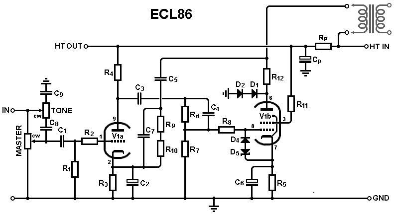
Even back in the valve days, sometimes you would see a part of say a combo triode-pentode drawn with incomplete envelopes to indicate that it was only part of the valve.
I have an excellent understanding of circuit operation Bob. I have used ltspice simulations first to get the circuit correct instead of building it first and then finding out it doesn’t work for some reason. And of course the simulation uses the same symbols as in the kicad schematic.
But in the case of kicad you are using a real dual comparator with 8 pins for example. When you build your circuit board these pins have to be connected to tracks on the circuit board. Tracks lead out of the pins. That is why in designing a circuit board it would be a lot simpler to use a rectangle with 8 pins for the actual schematic symbol. For simulation yes use the 3 pin symbols.
This is where kicad has gone wrong. They want to do simulations and at the same time make a circuit board. The two are incompatible. If you want to do simulations use ltspice. If you want to make circuit board tracks you have to use the real life components.
If you are designing your circuit board by hand you are using the real life symbol. The same goes for software design.
No. The THREE are incompatible.
There are Simulations, Schematics and PCB.
Three different workloads.
Three different results.
@BobZ posted a nice drawing of a component as an idea for you.
You won’t find a drawing like this in the Kicad libraries because it is neither a symbol (no pins) nor a footprint (no pads). It is a nice outline drawing of a component.
What you have written after seeing a schematic containing 4 comparators.
Distinguish between pins and wires at schematic and pads and tracks at PCB. It will be easier to understand what you are trying to say and if your thought are at schematic or at PCB.
During designing circuit board (PCB) we all have rectangle with 8 pads and we all agree that using this rectangle is the only way to go when designing PCB. But this have ABSOLUTELY NOTHING to how schematic should look like.
I disagree, and I think that millions of design engineers working since about 1971 would probably disagree. In 1971, I was a college sophomore who began as an intern in a work-study program. That work introduced me to TTL logic. The 7400 IC was a quad two input NAND gate, and I hand wired a breadboard based on the schematic diagram. The schematic diagram symbols were 4 gates drawn individually. They were not drawn in a package enclosure. (Thank you @m852 for providing this example for the LM339.) There is nothing wrong with such a symbol, but most design engineers find it more difficult to think and design with that sort of symbol than with the comparators drawn individually.
You may infer that I have been design engineering for almost 50 years. I have often used schematics with (symbols showing individual comparators or op amps or logic gates). Most of the time, I can design the board (or hand wire a breadboard) and it will work properly when I apply power. No need to use simulation for functionality of many of my designs. I will bet that MANY members of this forum have had similar experience.
Often in life, my opinion has been the odd one out for something or other. But here you are going against the proven experience of MANY engineers over MANY years. Of course other EDA programs are using similar symbols; nothing odd about KiCad in this regard. You are certainly entitled to your preferences, but any assertion that KICad is wrong in this regard does not carry much credibility.
It all depends on the requirements in my country there is a GOST standard in Europe, this is usually IPC if there are no requirements, then you can draw as convenient as possible … Below in the picture, for example, the designation of microcircuits and other parts according to GOST and I personally do not like readability and there are more strict Although DRC is used to it, this is a requirement for registration and is not a mistake if there are no clear tasks …
Thankfully ngspice exists and, hopefully on the next release, KiCad will be able to import and simulate ltspice’s stuff on all supported OSs out of the box.
Looks like transistors have to be redrawn. We need a big fat 2N3055 in a TO3 case. It has to be distinguishable from a TO92 case. And power resistors need to be beefy. 200 W and you’ll draw your cicuit on a DIN A2 sheet.
I personally wouldn’t want this. But if you need it, you can design your own components to scale, with al the original etchings and a bent pin here and there. I prefer my 7406 with a datecode 7244. It is easy!
The way schematics are being drawn has evolved over decades. It is a clear language understood all over the world. Don’t break it!
You can make your own two versions of LM339 symbols. One is separate: symbol with two or three components as shown by @jmk. Other version is symbol as shown by @m852. But my suggestion: use bigger box so smaller OpAmp symbol can fit inside.
I realize the two version has it own advantages. Me myself has some symbol with two versions.
I’m not Bob but, will attempt to answer… video below shows starting the symbol making process… you can’t see that I selected the Library folder but can see the message before selecting it (off screen)
Thanks to @BlackCoffee for getting into some details that I would not have.
In my opinion, making (at least some of) your own symbols is part of the pleasure of using KiCad. It means that you will no longer be constrained to use only what you can find. I like my symbols to have shorter pins for example (usually 50 mils) to pack the schematic more tightly. Otherwise, putting the +Power on one half of a dual and the ground on the other half as suggested is a completely reasonable option.
Below I show my two different symbols for BAW56. They both represent the same component and footprint. I use whichever symbol fits more nicely into the layout of the schematic diagram.
If I want it, no problem. I make it. Making symbols in KiCad is not difficult at all. You will enjoy using it more once you have learned to make your own symbols.
Since always (in Protel and in KiCad) I have them both in one symbol (using DeMorgan). Same for BAV70 and BAV99. Thanks to that I don’t need two names (-1, -2) so I can have only one record for each of these elements in my spreadsheet used to generate BOM.
I moved the discussion of De Morgan alternate symbols with some electronic and logic history to a new thread, as it’s drifting away from the original thread.


