Plugin for routing parallel tracks

Hi,

I have to route a design with 100+ tracks running side by side without crossings from one connector to the next. Is there a plugin which does this with respect to the track clearance?

If I do that by hand, the proposed track will linger around somewhere and not stay as close as possible to its neighbour, generating gaps and kinks, especially if the end point is not on a straight line but around ‘some corners’. I need a tool which routes the tracks side by side respecting the vias and edges and the clearance. One track should stick to the neighbour as my dog sticks to my foot, well most of the time.

Thank you
Cheers
Detlef

Don’t know if there is a plugin but I would start drawing one track, copy it, select both, copy again and so on. The seventh copy gives already 128 tracks. You can set the grid such that the gap fits.

  1. Draw a single track (can have some corners).
  2. Select it by dragging a box around it.
  3. [Ctrl + T] or select Create Array from the right mouse button popup menu.
  4. Enter some parameters.

Also:
Here is an old experiment I did by using block copy and paste to make lots of similar tracks.

One of the key points is that after those copied or array’d tracks have been connected to your connector, then they will get the net names of those connector pins, and the Interactive Router then will keep track of your clearances.

Euhm, You do have a schematic for this I hope?
It is a very bad Idea to try to do this without a schematic and a proper netlist.

1 Like

There is no plugin for doing such thing and current plugin API doesn’t support such interactive actions at the moment. Your best bet is using copy or array feature like others described.

Hi,

for parallel tracks around a corner the ‘inner’ lanes are much shorter than the outer ones, copy/paste is no option. This applies to more complicated structures as well.

The interactive Router should have an option ‘keep to your neighbouring track as close as possible’. This is not the routers behaviour. Even if I route track 1 and track 100, leaving an ‘canal’ in between I cannot ‘force’ the interactive router to squeeze in the 98 remaining tracks, it is wasting space so they wont fit.

Ok, thx for the fine software, it is useable nonetheless.

Cheers
Detlef

At some point I’d think with that many tracks the push/shove function would have to get them as close together as possible.

2 Likes

Can you give us a screenshot to clarify what you want?
Especially relative position of the connectors and what the corners look like.
Do you have 45 degree bends, or some other angles?
How important is it to you that track spacing is kept in those 45 degree bends?
Is this for design of a flex cable? Is it single layer,double sided or other?

I don’t know how many tracks the interactive router will push in one go, but I’m still thinking it should be relatively easy to do this with a combination of copy / paste and array and interactive router.

Some other things that help:
Use a custom grid that fit with the trackwidth + clearance you want to use.
Make use of the ability to lock some tracks, so the interactive router won’t move those tracks.

I’ve done a little experiment with two 40 pin connectors, and the result looks like:

It is a bit of a repetitive job. I tried to copy and then merge sections, but Pcbnew / Edit / Cleanup Tracks and Vias does not work as good as I hoped.

The interactive router happily shoves all 40 track segments in one go, so that’s a plus.

Another function that really would have been handy is the ability to move one of the connectors, and then stretch all attached tracks.

If you want to toy with it:
2021-04-17_asdf_100pin_connector.zip (9.9 KB)

1 Like

I’ve experimented a bit more, and this is what I’ve found to work best in this particular case:

First set the grid to the spacing you want, and then draw a single track with two of the 45 degree corners. The stubs should be long like in this screenshot:

Then use copy & paste to make a few of them. Here I copied it 4 times to make a total of 5:

During paste, you give each copy a gid offset of one grid size in both X and Y direction:

Then repeat. I took the block of 5 and pasted it a few times, then took the whole block and copied & pasted it again until have plenty of tracks:

Now, the important part. Select all horizontal tracks, (Dragging a box from left to right only selects fully enclosed items, while dragging a box from right to left also selects everything crossing the box boundaries)
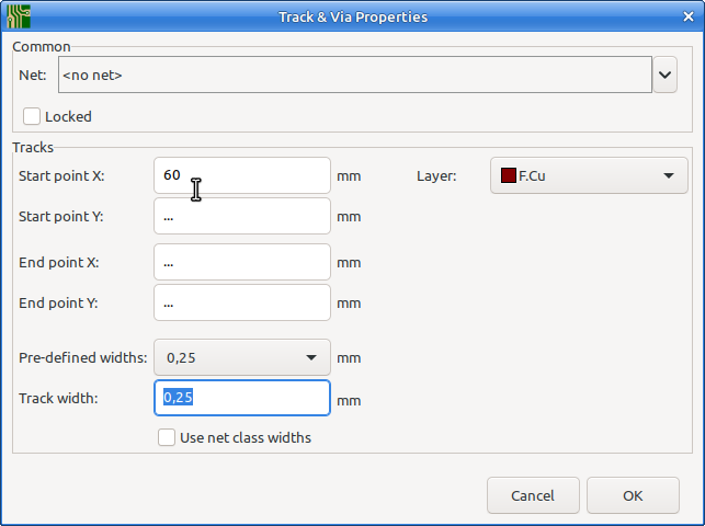
When the tracks are selected, press e for edit then enter a suitable number for “Start point X”. Here I choose 60.
image

The result:
image

Now you can simply move the connector by a pad and then place it on the corresponding track segment.
Make sure you see the small white circle around the cursor position. This is an indication that KiCad has found a snap point. If you work on the grid, this is not so important, but it may in other situations.
image
KiCad can use several items as “magnetic points” to snap to. You can find these in Pcbnew / Preferences / Preferences / Pcbnew / Magnetic Points

Repeat the above for the other end of the wire segments, but now enter a suitable number for the “End point Y:” coordinate.

It’s probably clear now why I started with very long stubs. It makes them easy to select by dragging a single box. If you do not do this, then you can hold the shift key and drag a box (Either left or right) to expand your selection, or click a single item to toggle it into or out of the selection.

Finally:
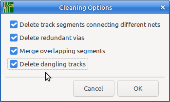
After you’ve placed both connectors on the end, do: Pcbnew / Edit / Cleanup tracks and Vias and make sure the “Delete dangling tracks”" checkbox is on:
image
This removes all extra tracks and only leaves the ones connected to your connectors.

With this method you can draw such things in a few minutes, and it is adoptable to lots of similar situations. It would be hard to do this quicker or better with a script.

This is one of the situations in which an auto router may be of help. KiCad does not have an built in autorouter, but it can export to an external autorouter such as FreeRouter. With a bit of bad luck though it makes a tangled mess of it and cleaning up afterwards is more work then using the copy & Paste with adjusting coordinates I described above.


[Edit]
Some additions related to:

With the Copy & Paste method I did above, al the 45 degree tracks end up with the same length (They are copies, duh), and this result in different spacing for the angular tracks. To change the spacing with the interactive router, you just hover over one of the outer tracks and push it inwards. I had no trouble pushing 40 tracks aside. You can also make use of the Locking function (From the right mouse button popup menu, or L as shortcut key. to lock a track and then push the others until they will go no further.

The behavior is that it just moves a single track, and pushes stuff aside when needed, and as a result they may end up lined up nicely, but that’s a side effect.

The real solution for this, is called a “guided autorouter” (and it also goes by other names). This is however not implemented in KiCad.

2 Likes

Hi Paul,

thx for the elaborate answer!

The pcb is four layer.
Track width is 0.11mm, clearance ist 0.19mm, user grid is 0.3mm, that fits nicely.
Clearance has to be maintained at 45 deg tracks.
Setting start points of tracks and ‘box from the left’ vs. ‘box from the right’ is convenient, did not know this.

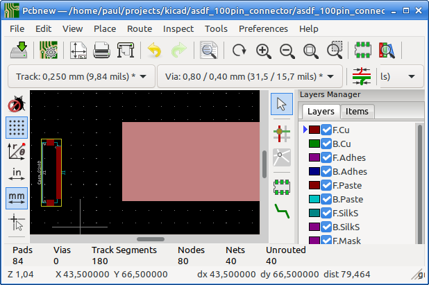
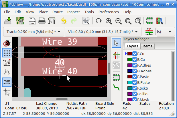
Here are two screenshots.
First shows what I want to do: Many parallel tracks. I want to keep the new track as close as possible to the other ones.
The second screenshots shows what happens: The track of the interactive router disappears in the wild, maybe inspired by the end point. That happens especially at situations where the whole set of tracks shows some displacement. I have to interrupt the routing and give it a new start.
This routing costs a lot of time and is generating the ‘gaps and kinks’, see the screenshot. It is no showstopper for the layout but it does not look nice.

THX a lot.
Cheers
Detlef

pic2|690x454

Tnx for the screenshots.
Gives me a better idea of what you’re making, although the details are a bit fuzzy. I can’t see what you did before you got to that screenshot and other details.

First a remark about your parallel tracks.
I do not understand why you find this important. They may look pleasing to the eye, but they are actually bad from an electrical viewpoint because it increases inductive and capacitive coupling between those signals. A larger clearance between the tracks helps, but there is not always room for that on the PCB. A trick often used is to route your vertical tracks upward from the connector, then use vias, and then route the horizontal tracks in a different order as the vertical tracks. This distributes the coupling between more different tracks, and it is much more likely that those couplings stay below an acceptable threshold.
For your design you could partly adapt the “L-shaped tracks” and the way I drew them, but you will also want to make use of other capabilities of KiCad.

For a part of the routing you probably want to change the settings of the interactive router. Maybe even disable the push and shove capability. The setting is in: Pcbnew / Route / Interactive Router Settings…

You can also make smart use of Pcbnew / Edit / Cleanup Tracks & Vias… For example, you can draw such a big L wit lots of tracks, then make a copy of it and block rotate it 180 degrees for the tracks on the south side of your connector. Then you can block move those parts and (maybe manually) connect them to the connector. In between you can do the Cleanup Tracks & Vias to clean up shorts which you made by the block copy & paste method.

The most important idea here is to treat your PCB as you would do in a generic drawing program, and not from the viewpoint of a PCB and drawing tracks one by one. This is a different way of thinking, and will take some time to adopt to.

Technically there is, but only for two tracks at once. The Differential Pair router. But since it is only 2 tracks it doesn’t really apply in this application.

Euhm, no. Not really.
With differential pair routing, you manually route one of the tracks, and the other just keeps hugging it until the pads on the end are reached.

With the “Guided Autorouter” you give a general path for a set of signals, and the autorouter determines final position for the all of them (Usually signals that have similar meaning, such as an address or data bus).

Ok, I didn’t quite get that distinction. Thanx for the edification. :slight_smile:

The setup for the differential pair should be also ok for parallel tracks: not only one track keeps hugging to the routed one but many tracks keep hugging to it.

Cheers
Detlef

1 Like

This topic was automatically closed 90 days after the last reply. New replies are no longer allowed.