I’ve experimented a bit more, and this is what I’ve found to work best in this particular case:
First set the grid to the spacing you want, and then draw a single track with two of the 45 degree corners. The stubs should be long like in this screenshot:
Then use copy & paste to make a few of them. Here I copied it 4 times to make a total of 5:
During paste, you give each copy a gid offset of one grid size in both X and Y direction:
Then repeat. I took the block of 5 and pasted it a few times, then took the whole block and copied & pasted it again until have plenty of tracks:
Now, the important part. Select all horizontal tracks, (Dragging a box from left to right only selects fully enclosed items, while dragging a box from right to left also selects everything crossing the box boundaries)
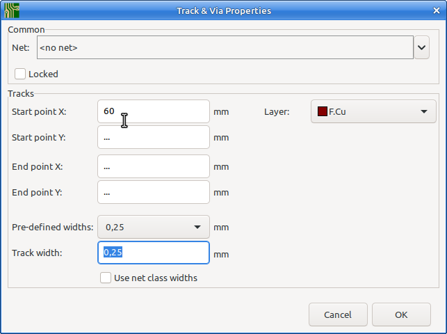
When the tracks are selected, press e for edit then enter a suitable number for “Start point X”. Here I choose 60.

The result:

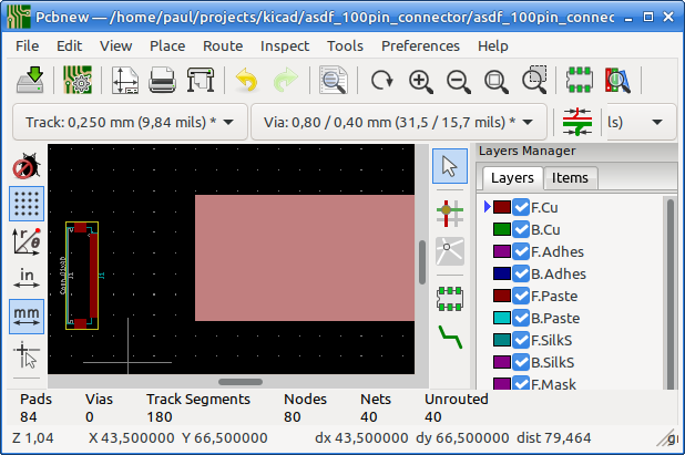
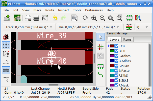
Now you can simply move the connector by a pad and then place it on the corresponding track segment.
Make sure you see the small white circle around the cursor position. This is an indication that KiCad has found a snap point. If you work on the grid, this is not so important, but it may in other situations.

KiCad can use several items as “magnetic points” to snap to. You can find these in Pcbnew / Preferences / Preferences / Pcbnew / Magnetic Points
Repeat the above for the other end of the wire segments, but now enter a suitable number for the “End point Y:” coordinate.
It’s probably clear now why I started with very long stubs. It makes them easy to select by dragging a single box. If you do not do this, then you can hold the shift key and drag a box (Either left or right) to expand your selection, or click a single item to toggle it into or out of the selection.
Finally:
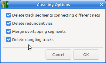
After you’ve placed both connectors on the end, do: Pcbnew / Edit / Cleanup tracks and Vias and make sure the “Delete dangling tracks”" checkbox is on:

This removes all extra tracks and only leaves the ones connected to your connectors.
With this method you can draw such things in a few minutes, and it is adoptable to lots of similar situations. It would be hard to do this quicker or better with a script.
This is one of the situations in which an auto router may be of help. KiCad does not have an built in autorouter, but it can export to an external autorouter such as FreeRouter. With a bit of bad luck though it makes a tangled mess of it and cleaning up afterwards is more work then using the copy & Paste with adjusting coordinates I described above.
[Edit]
Some additions related to:
With the Copy & Paste method I did above, al the 45 degree tracks end up with the same length (They are copies, duh), and this result in different spacing for the angular tracks. To change the spacing with the interactive router, you just hover over one of the outer tracks and push it inwards. I had no trouble pushing 40 tracks aside. You can also make use of the Locking function (From the right mouse button popup menu, or L as shortcut key. to lock a track and then push the others until they will go no further.
The behavior is that it just moves a single track, and pushes stuff aside when needed, and as a result they may end up lined up nicely, but that’s a side effect.
The real solution for this, is called a “guided autorouter” (and it also goes by other names). This is however not implemented in KiCad.


