PCB layout strategy

Mechanical ‘hysteresis’ is from the ‘Backlash’ - in Milling, it’s when the direction reverses and the travel in a ‘Repeating’ manner does Not fully travel to the exact same ‘value’ (if you want to call it that). It’s commonly due to mechanical ‘Slop’ , ‘Wear’…etc.

My Mill (as does most Mill’s) has inherent ‘Backlash’ of some amount, mine has 0.001 to 0.002 Inch of Backlash.
The ‘setup’ has Controller Adjustment/Compensation for it and determining the Setting-Value is based on measuring travel-direction changes in testing (typically at Maintenance time) .

If one were to Plot this, it would look just like most any other Hysteresis

NOTE:
I stopped adjusting Backlash about 10yrs ago after determining that moderate usage always proved out the Backlash grew to about 0.001inch and that is what I set the Compensation to. Yes, I can tighten it up but it’s not important for my projects.

Screenshot is ‘How to test Backlash’

ADDED:
I use LM386 in some Audio projects (I’m also a Musician and fiddle with Stomp-Boxes…)

There’s nothing wrong with using someone’s design but, for me, when it comes to using Chips/parts/etc, I prefer referring to manufacturing Spec’s and starting with their recommended Circuits and building them (on BreadBoards before doing a PCB).

Here’s link to Spec and you can start at page 12 and review the recommended circuit(s) for various Gains/Distortion/Oscillation…

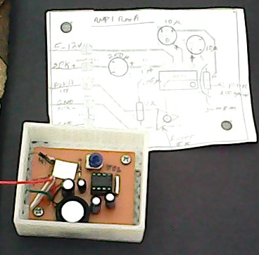
An old photo of my first LM386 test on BreadBoard… and on PCB. I still use them!


LM386_AMP

1 Like

First off, never presume some open-source author knows what they are doing. There is a lot of shitty advice out there from self-proclaimed experts who are a product of the look-at-me, I-know-everything, selfie generation. I would put a 10uF and 0.1uF bypass at the chip to ensure clean supply.

Yes, connect your ground plane to batt negative. I don’t see a power switch – it looks like plugging an adapter into the coax jack disconnects the battery, like most of the 9V-center-negative stomp box designs, but no other switch to disconnect battery? I think I have seen neutriks with extra switches that may disconnect power when guitar is unplugged.

Split supply does not apply here as your circuit is designed for single supply (I presume your schematic is like the one in the link you provided). An interesting looking circuit – I have always liked JFETs.

Splitting supply is when you want to run opamps that need pos/neg rails instead of single-supply opamps. With a single supply (eg: 0 to 9V) you need to create a half-supply reference voltage (not critical voltage but typically half supply eg: 4.5V) to bias the opamp inputs which is as simple as a voltage divider and filter cap. This provides a clean ref voltage but high source impedance (eg: if you use two 10k resistors in the divider the result is the thevenin equiv of a 4.5V source with 5k series impedance). This is perfectly fine for low-power opamp circuitry.

When you need a split supply with a low impedance (need to sink/souce current during operation) you often see the TLE2426 used in designs like the popular cmoy headphone amp:

https://electronics-diy.com/electronic_schematic.php?id=797

https://www.ti.com/document-viewer/lit/html/SSZTAI6

Attached is a little stomp box I did years ago with a base pcb and an effects pcb that plugs into it. A couple of things to note: I used a resistance-multiplier opamp input which provides a 10meg input impedance to not load down the guitar pickups (which can be 100k). This way you don’t have resistor noise of a 10meg resistor as this uses 100k/10k/100-ohm resistors. I didn’t believe this could have 10meg in until I simulated and then built and tested it. Resistance multiplier is an interesting circuit. Probably overkill here but I wanted to try it out.

190-8002-A-pedal-SCHEMATIC.pdf (188.3 KB)

Also note that I want my jack symbols to show all the detail of switches, which contacts are posistioned for tip/ring/sleeve… I hate cryptic schematics that tell you nothing and require you to look parts up to figure out what is going on.

I am using the 9V as the positive rail and using a buck reg configured as an inverter to generate a negative (~-9V) rail. I used the commonly-available 3PDT stomp switch which provides power switching and true bypass. Added an optional 3.5mm line out.
The 100-ohm R112 is important to drive the capacitance of the cable to the guitar amp and not piss off the opamp.
Anyway, fyi.

1 Like

My general philosophy is that, if someone knows enough to design a circuit, they probably know more about circuit design than I do.

1 Like

This topic was automatically closed 90 days after the last reply. New replies are no longer allowed.