Hello @maui, first I would like to thank you for the creation of this plugin.
I designed a PCB with KiCad and want to import it in FreeCAD. Everything but the import of the filled zones work out of the box. After a little investigation it seems to me that there is a problem if a copper zone fill is active on more than one layer (in my example top and bottom). I have attached a minimal example.
To reproduce, open in KiCad and make sure the copper zone fill is active on only one layer. Import in FreeCAD including the copper works as expected.
Change the zone to be active on Top and Bottom layer, import again in FreeCAD and the copper zone is not included.
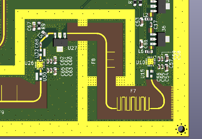
I have another question concerning the mask layers. Is it possible to see them in FreeCAD? I’m making an aluminum housing for the filters in the previous posts and I would like to be able to see the exposed areas of the pcb to ensure there are no mistakes. You can imagine it like this:
The exposed ground areas will have metal walls contact them from the housing.
Hi @dom11990, have you started to write a little tutorial?
I would be very happy to add it to ksu WB.
I’m going to see if I can add the option to load a Mask area inside FreeCAD.
Do you have a demo board to test it? (you can send it in PM if you prefer).
hey @maui I have to admit that I have not. I will though! What format would you prefer? Should I put everything into a Writer document and you add the styling you have for your other documentation? Where should I post it? I will do it this weekend.
@maui yes I have the text and pictures. It needs some polish though. Still working on it. Unfortunately, a work deadline got moved up 3 weeks so I’m in crunch mode now and have to push this a bit I will send you what I have and perhaps you could at least comment on my workflow?
Hi Maui,
I’ve been using Kicad StepUp for a long time and think it’s a great tool, the improvements you have been making have been a great improvement.
I’m having an issue with a downloaded model were the face colours all get messed up after I have set them the way I’d like and then export the model via Kicad StepUp 178-009-613.step.zip (334.0 KB) .
All I’m doing is the following:
Importing the attached step file into a new Kicad V0.19 document.
Select the imported body and choose the “Set colors…” from the context menu.
Select all faces and change the color to “Metal Silver” 129,129,129.
Select the different faces I which to change the colors of. For example change the pins to “Gold Pins” 219,188,126.
Select “OK”
Save the file.
Export to “3d Model to Kicad” via Kicad StepUp v10.1.3.2, use all default values or export.
Once the Step file is generated the model will change colors.
Are you able to look at the attached model and indicate what I am doing wrong, If possible could you even correct the model so that I can color and export it successfully.
hi @kkeeley
I’ve changed the routines to add a new feature in step export, but it seems I’ve added an issue with my latest update.
I will have a look asap.
For the moment you can use this commit kicadStepUpMod previous commit
Thanks for reporting
@kkeeley
Hi Ken, I’ve reverted the commits to avoid, ATM, the STEP transparency attribute …
You can update the version and it should work as previously.
I’ve also added this function to the Undo FC history of commands.
@maui
Thanks for the quick work around, I’m glad it wasn’t me that was doing something wrong. Hopefully you will resolve the issue quickly and can then restore the features lost by the reverting the code back to before the issue.
I’m making an aluminum housing for the filters in the previous posts and I would like to be able to see the exposed areas of the pcb to ensure there are no mistakes.
Perhaps you can use the power of FreeCAD? Import the finished pcb into FreeCAD with the KiCADstepUP tool, then import STEP model(s) of your aluminum parts, and then use one of FreeCAD’s assembly workbenches to assemble the whole thing. You can make the aluminum parts a bit transparent, so you can observe if there are any problems.
Hey! I’m trying to design a EMI/RFI shield for RF board, SatNOGS-COMMS and i’m stacking in footprint export from FreeCAD to KiCad. The FreeCAD model is placed here.
The problem is, when i create a sketch with RF_PolyLined Sketch the conversion to footprint, it has a result of unified plane and not the shape of sketch.
I would like to create a guide how to go from KiCad to FreeCAD and back to KiCad in order to create the EMI/RFI shield.
Then in your user case, you need to break the shape, even with a small gap, and then create the poly line shape to be converted to kicad footprint.
Then you need to add a small circle inside the sketch to create the reference pad

 I will send you what I have and perhaps you could at least comment on my workflow?


