I’m looking to create a simple PCB (with 8 LED tactile switches with resistors, connected to a row of pins, possibly Arduino controlled). I need help with some basics. I’ve been using KiCad for a week now and have a starting knowledge with schematics and footprints. However, the first issue I ran into was the component symbol I wanted to use in the schematic. I could not find it or anything similar in the libraries.
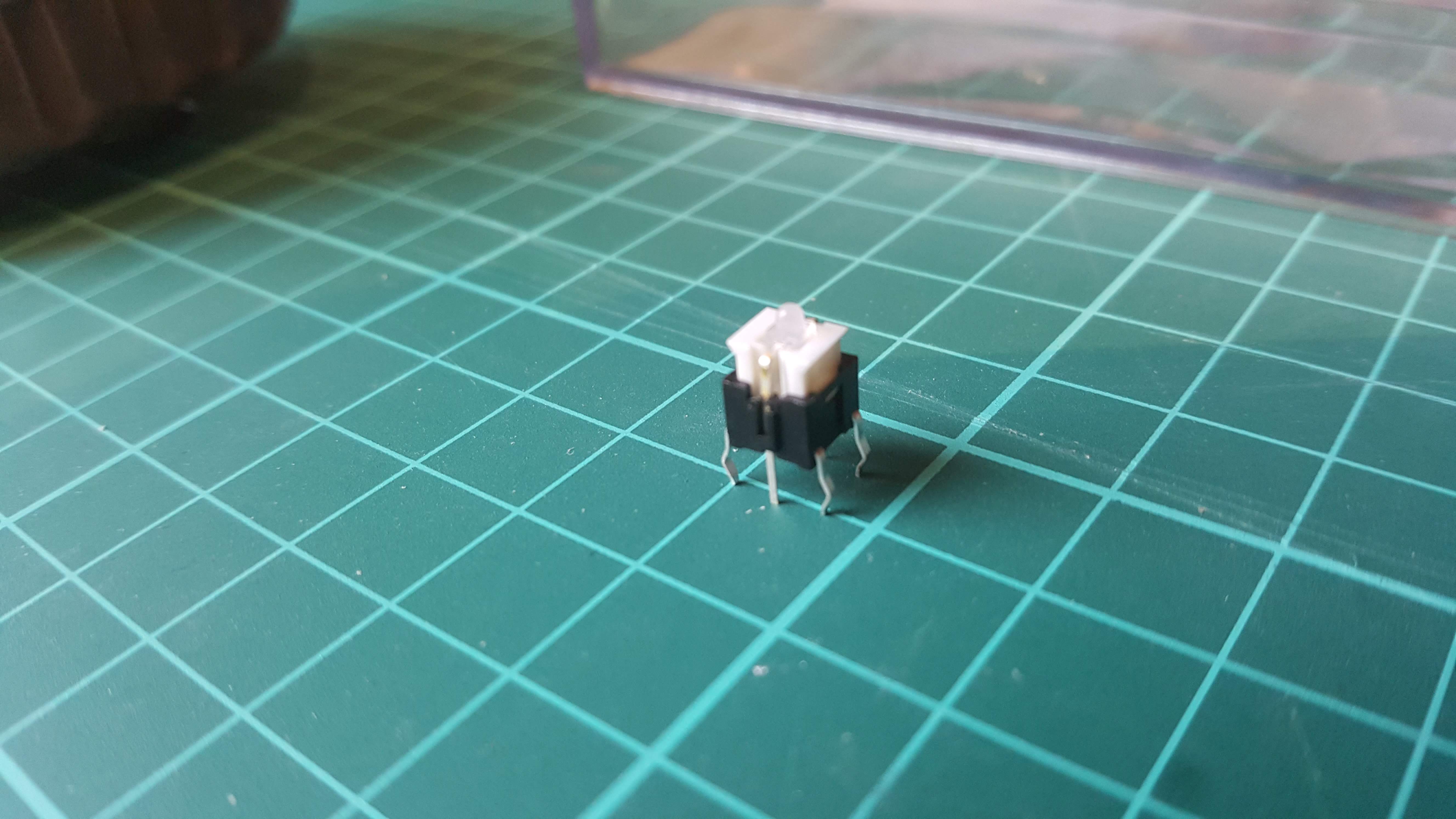
It’s probably a version of the OMRON B3E-11-GREEN but it looks a slightly different manufacture. Anyone seen anything similar in the libraries? I have a very basic spec sheet on the part (from ebay!)
I went through some basic tutorials and had a go at creating my own schematic for it. I also measured the pins and made a footprint. However I don’t think I was experienced enough to correctly create custom designs.
Anyone who could help me along here with a few starting steps and the best overall approach for working with this component, would be much appreciated!
I am probably a bit biased here but i really have to disagree. I seldom get a footprint contribution that is first time right so if you do not have somebody else checking your work then it is quite unlikely that you will not make a silly mistake. (Luckily for us most minor mistakes are not really dealbreakers with todays manufacturing techniques) Which means taking a footprint from a trusted source and double checking it might be the better option to be honest.
You posted a photograph of the part, not a hypertext link to a datasheet. I see 4 leads in the photograph. I infer there are a total of 6 leads. Give us more information.
I suggest you review the video at
Even though BuildElectronicCircuits made this video using kicad 4, it will IMHO give you an overview of the steps you need to take in kicad 5, the current version, to create both a schematic and a
corresponding PCB.
Also read Rene Poschl’s tutorial on how (and why) to make a footprint:
Welcome to this Forum & Thank You for giving KiCAD a try!
Two things would help us answer your question:
Your photo is a good start. Please attach a copy of your part’s Data Sheet, even if it’s a marginal-quality scanned image. Any manufacturer’s ID or part numbers would also be helpful. (This Forum has members from all over the world, so it’s possible that somebody recognizes a part available only in their own locality, and not listed by the major distributors from the U.S. or Europe.)
If it’s permitted, attach a copy of your project files. (We know that non-disclosure policies and corporate security practices often prevent this.) Even a screen-capture of the relevant section of the schematic or layout can provide information helpful to those assisting you.
As a new Forum member, you have limited ability to attach files. One workaround is to attach one file to each of several posts. Or, spend a little time reading through a few threads; issue a few “Likes”; post a few comments. The Forum will automagically upgrade your privileges when it seems obvious that you are a reasonable person, and not here to SPAM us or start arguments. You can also beg, plead, and grovel before one of the Moderators (such as @hermit ) to upgrade your privileges. I don’t know what his favorite brand of malt beverage is, but providing him with a serving or two might be another way to advance your status on the Forum.
Now for your main question . . .
I would start by looking at the symbols available in the standard KiCAD library. I don’t know if any of those symbols include illumination. If not, you need to create your own symbol. That will take a little time, but it’s not especially difficult. I’d start with an existing Switch symbol, and add an LED symbol. The resulting symbol will be a multi-unit symbol, with the two sections NOT interchangeable.
Save your new symbol to your personal symbol library!
Use the same approach for the footprint. Your part’s pin spacing and layout is probably used by at least one other manufacturer, so browse the footprints in “Button_Switch_THT.pretty” until you find one with similar dimensions. Modify it, or add pin(s), if necessary.
Save it to your personal Footprint library!
The Forum’s “FAQ” topic has several articles that may be helpful to you. They tend to be well written and profusely illustrated with screenshots. At least look through the list of topics to see if any seem to apply to your situation.
Thank you for correcting my URL. I edited my previous post accordingly.
P.S. I found this document on Kicad Library Convention https://www.kicad.org/libraries/klc/
helpful. It revealed to me the highly-organized way in which the components are named in the parts libraries. You may find it helpful too.
Many thanks for the replies! Yes that Youtube video is where I started, I have viewed it many times. It is just a bit different for dealing with my component, the video goes shows the process with simple Library components. However, I am doing my best to take everyones advice here thanks. I can confirm that I have a 6 lead component, I will try and attach the very limited data sheet and my project so far.
Thanks Bobc, Thats the data sheet!! The switches I have, have orange LEDs but its now easy to check that I made my own ‘guessed’ symbols and footprint correctly. looks like I got the pins correct with the DMM.
With bobc’s data sheet, above I’ll fine tune my created symbol and save it in the pers Library. I’ll do the same with (now a more accurate) footprint. I guess the next step is to create all symbols/circuit in a full schematic.


