Hello Community,
iam currently designing a board that contains an 100MBit Ethernet connection.
and thats the first time iam doing ethernet things.
so i have had a look at a App-Note of the PHY chip:
it contains a lot of good information -
and for me its clear i have to do a differential pair for the TX+/TX- and RX+/RX- traces.
i know that i can use the differential pair rooting tool.
i also know that i have to do a 50Ohm impedance per trace -
so i opend the KiCad PCB Calculator and tried to get some values out of this
as input parameters i looked up the material datasheet from my board house and got:
Er 4.6
TanD 0,015
my board thickness is 1,5mm (base material)
and 35um Cu
and anded up with:
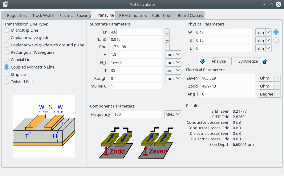
so width: 0,47mm
spacing: 0,15mm
the trace width seams really heavy to me.
i have also tried it with this calculator:
http://www.eeweb.com/toolbox/edge-coupled-microstrip-impedance/

but there it came to 0,7mm width traces.
i have found a document that says:
width 0,25mm
separation: 0,25mm
separation between RX-pair and TX-pair: 0,5mm (or gnd)
currently my trace will be about 35mm long.
(and additionally i have to add some ESD things so they will get slightly longer)
one question that came to my mind is - how much clearance should i leave around the trace pair? (to the next pair and to the ground plane.
is here somebody that has some experience and is can share some tips?
iam open to every bit of information to understand better what is relevant and how to do it correct 
sunny greetings
stefan